本文主要是介绍OpenGL ES初探(四) -- 用OpenGL画正四面体,正方体,球,希望对大家解决编程问题提供一定的参考价值,需要的开发者们随着小编来一起学习吧!
OpenGL ES初探(四) – 用OpenGL画正四面体,正方体,球
目录
- OpenGL ES初探(四) – 用OpenGL画正四面体,正方体,球
- 目录
- 准备工作
- 添加初始代码
- 结构说明
- 添加初始代码
- 构建ShapeProgram
- 构思
- 构建BaseShape
- 构建ShapeProgram实例
- 创建正四面体
- 创建正方体
- 创建球形
- 引入透视投影
- 增加触摸事件
- 背面裁剪
- 卷绕
- 示例源码
- 参考
- 相关链接
- 附录
- 最初的源码
- 附1
- 附2
- 附3
- 附4
- 最初的源码
- 准备工作
准备工作
添加初始代码
构建包
com.yxf.variousshape3d将上篇博客的源码1中的MainActivity、CommonUtils还有Point复制到
com.yxf.variousshape3d包下;将res/raw/中的着色器代码复制过来.在
com.yxf.variousshape3d下添加MyRender类如下
package com.yxf.variousshapes3d;import android.content.Context;
import android.opengl.GLSurfaceView;import com.yxf.variousshapes3d.programs.Program;import java.util.List;
import java.util.concurrent.CopyOnWriteArrayList;import javax.microedition.khronos.egl.EGLConfig;
import javax.microedition.khronos.opengles.GL10;import static android.opengl.GLES20.GL_BLEND;
import static android.opengl.GLES20.GL_COLOR_BUFFER_BIT;
import static android.opengl.GLES20.GL_ONE_MINUS_SRC_ALPHA;
import static android.opengl.GLES20.GL_SRC_ALPHA;
import static android.opengl.GLES20.glBlendFunc;
import static android.opengl.GLES20.glClear;
import static android.opengl.GLES20.glClearColor;
import static android.opengl.GLES20.glEnable;
import static android.opengl.GLES20.glViewport;public class MyRenderer implements GLSurfaceView.Renderer {private Context context;private List<Program> programs = new CopyOnWriteArrayList<Program>();public MyRenderer(Context context) {this.context = context;}public void addProgram(Program program) {programs.add(program);}public void clearProgram() {programs.clear();}@Overridepublic void onSurfaceCreated(GL10 gl, EGLConfig config) {glClearColor(1f, 1f, 1f, 0f);glEnable(GL_BLEND);glBlendFunc(GL_SRC_ALPHA, GL_ONE_MINUS_SRC_ALPHA);for (Program program : programs) {program.onSurfaceCreated(context);}}@Overridepublic void onSurfaceChanged(GL10 gl, int width, int height) {glViewport(0, 0, width, height);for (Program program : programs) {program.onSurfaceChanged(width, height);}}@Overridepublic void onDrawFrame(GL10 gl) {glClear(GL_COLOR_BUFFER_BIT);for (Program program : programs) {program.onDrawFrame();}}}- 在
com.yxf.variousshapes3d包下创建包programs,然后在programs包下添加Program类如下
package com.yxf.variousshapes3d.programs;import android.content.Context;import com.yxf.variousshapes3d.CommonUtils;import static android.opengl.GLES20.GL_BLEND;
import static android.opengl.GLES20.GL_ONE_MINUS_SRC_ALPHA;
import static android.opengl.GLES20.GL_SRC_ALPHA;
import static android.opengl.GLES20.glBlendFunc;
import static android.opengl.GLES20.glEnable;
import static android.opengl.GLES20.glUseProgram;public abstract class Program {protected int program;private int vertexResourceId, fragmentResourceId;private ShaderCallback shaderCallback;public Program() {}public void onSurfaceCreated(Context context) {ShaderCallback callback = getShaderCallback();this.vertexResourceId = callback.getVertexResourceId();this.fragmentResourceId = callback.getFragmentResourceId();shaderCallback = callback;if (callback == null) {throw new RuntimeException("the shader callback of program can not is null , program : " + getClass().getName());}String vertexShaderSource = CommonUtils.readTextFromResource(context, vertexResourceId);String fragmentShaderSource = CommonUtils.readTextFromResource(context, fragmentResourceId);int vertexShader = CommonUtils.compileVertexShader(vertexShaderSource);int fragmentShader = CommonUtils.compileFragmentShader(fragmentShaderSource);program = CommonUtils.linkProgram(vertexShader, fragmentShader);shaderCallback.initialize(program);}public void onSurfaceChanged(int width, int height) {}protected void useProgram() {glUseProgram(program);}public void onDrawFrame() {useProgram();shaderCallback.prepareDraw(program);}public abstract ShaderCallback getShaderCallback();interface ShaderCallback {int getVertexResourceId();int getFragmentResourceId();void initialize(int program);void prepareDraw(int program);}
}
结构说明
这次结构和上次结构差异还是有点大的
这次我们基于OpenGL的program扩展出来Program类
然后以Program为单位,在MyRenderer中draw出每个program
构建ShapeProgram
构思
为了避免太多的重复工作,我们不需要每个立体图形都构建一个Program类,我们可以先构建ShapeProgram类和BaseShape类,ShapeProgram负责构建场景和处理矩阵,BaseShape类负责绘制图形,然后将BaseShape添加进ShapeProgram中达到解耦和简化的目的.
构建BaseShape
我们在com.yxf.variousshapes3d包下添加shapes包,然后在shapes包下添加BaseShape类如下
package com.yxf.variousshapes3d.shapes;import com.yxf.variousshapes3d.Point;import java.nio.FloatBuffer;import static android.opengl.GLES20.GL_FLOAT;
import static android.opengl.GLES20.glVertexAttribPointer;public abstract class BaseShape {public static final int BYTES_PER_FLOAT = 4;public static final int POSITION_COMPONENT_COUNT = 3;public static final int COLOR_COMPONENT_COUNT = 4;public static final int STRIDE = (POSITION_COMPONENT_COUNT +COLOR_COMPONENT_COUNT) * BYTES_PER_FLOAT;protected int aPositionLocation;protected int aColorLocation;protected Point center;protected Object mLock = new Object();public BaseShape(Point center) {this.center = center;}public void setLocation(int aPositionLocation, int aColorLocation) {this.aPositionLocation = aPositionLocation;this.aColorLocation = aColorLocation;}public final void draw() {preDraw();synchronized (mLock) {FloatBuffer vertexData = getVertexData();vertexData.position(0);glVertexAttribPointer(aPositionLocation, POSITION_COMPONENT_COUNT, GL_FLOAT,false, STRIDE, vertexData);vertexData.position(POSITION_COMPONENT_COUNT);glVertexAttribPointer(aColorLocation, COLOR_COMPONENT_COUNT, GL_FLOAT,false, STRIDE, vertexData);drawArrays();}afterDraw();}public void initialize() {synchronized (mLock) {initWithoutLock();}}public static FloatBuffer encodeVertices(float[] vertices) {FloatBuffer vertexData = ByteBuffer.allocateDirect(vertices.length * BYTES_PER_FLOAT).order(ByteOrder.nativeOrder()).asFloatBuffer();vertexData.put(vertices);return vertexData;}public abstract void initWithoutLock();protected abstract FloatBuffer getVertexData();protected abstract void drawArrays();protected abstract void preDraw();protected abstract void afterDraw();}
由于OpenGL在Android中其实是有个渲染线程的,所以在其中数据处理的地方加了锁.
构建ShapeProgram实例
我们再com.yxf.variousshapes3d.programs包下创建ShapeProgram类,继承于Program类如下
package com.yxf.variousshapes3d.programs;import com.yxf.variousshapes3d.R;
import com.yxf.variousshapes3d.shapes.BaseShape;import java.util.List;
import java.util.concurrent.CopyOnWriteArrayList;import static android.opengl.GLES20.glEnableVertexAttribArray;
import static android.opengl.GLES20.glGetAttribLocation;
import static android.opengl.GLES20.glGetUniformLocation;
import static android.opengl.GLES20.glUniformMatrix4fv;
import static android.opengl.Matrix.orthoM;public class ShapeProgram extends Program implements Program.ShaderCallback {private static final String A_POSITION = "a_Position";private int aPositionLocation;private static final String U_MATRIX = "u_Matrix";private final float[] projectionMatrix = new float[16];private int uMatrixLocation;private static final String A_COLOR = "a_Color";private int aColorLocation;private List<BaseShape> shapeList = new CopyOnWriteArrayList<BaseShape>();public ShapeProgram() {super();}@Overridepublic void onSurfaceChanged(int width, int height) {super.onSurfaceChanged(width, height);final float aspectRatio = height / (float) width;orthoM(projectionMatrix, 0, -1, 1, -aspectRatio, aspectRatio, -1, 1);}public void addShape(BaseShape baseShape) {shapeList.add(baseShape);baseShape.initialize();}public void clearShapeList() {shapeList.clear();}private void initShapeList(float aspectRatio) {clearShapeList();}@Overridepublic void onDrawFrame() {super.onDrawFrame();for (BaseShape baseShape : shapeList) {baseShape.setLocation(aPositionLocation, aColorLocation);baseShape.draw();}}@Overridepublic ShaderCallback getShaderCallback() {return this;}@Overridepublic int getVertexResourceId() {return R.raw.shape_vertex_shader;}@Overridepublic int getFragmentResourceId() {return R.raw.shape_fragment_shader;}@Overridepublic void initialize(int program) {aPositionLocation = glGetAttribLocation(program, A_POSITION);uMatrixLocation = glGetUniformLocation(program, U_MATRIX);aColorLocation = glGetAttribLocation(program, A_COLOR);glEnableVertexAttribArray(aPositionLocation);glEnableVertexAttribArray(aColorLocation);}@Overridepublic void prepareDraw(int program) {glUniformMatrix4fv(uMatrixLocation, 1, false, projectionMatrix, 0);}
}
以上的OpenGL的方法使用在之前博客中都有说明,故不再赘述.更多的是结构的变化,建议下载源码分析,更容易理解.
值得注意的一点是,BaseShape的COLOR_COMPONENT_COUNT常量设置成了4,这是我们引入了颜色的第四个分量a,而为了开启OpenGL透明度还在MyRenderer.onSurfaceCreated中添加了
glEnable(GL_BLEND);
glBlendFunc(GL_SRC_ALPHA, GL_ONE_MINUS_SRC_ALPHA);
两个方法
创建正四面体
基础类都创建完了我们开始创建实际的绘制类吧
先绘制正四面体,在com.yxf.variousshapes3d.shapes中添加Tetrahedron类继承于BaseShape
package com.yxf.variousshapes3d.shapes;import android.graphics.Color;import com.yxf.variousshapes3d.Point;import java.nio.ByteBuffer;
import java.nio.FloatBuffer;import static android.opengl.GLES20.GL_TRIANGLES;
import static android.opengl.GLES20.GL_UNSIGNED_BYTE;
import static android.opengl.GLES20.glDrawElements;public class Tetrahedron extends BaseShape {private float[] vertices;private FloatBuffer vertexData;private float radius;private ByteBuffer positionBuffer;private int coordinateCount;public Tetrahedron(Point center, float radius) {super(center);vertices = new float[(COLOR_COMPONENT_COUNT + POSITION_COMPONENT_COUNT) * 4];this.radius = radius;//绘制时所需顶点个数coordinateCount = 3 * 4;}@Overridepublic void initWithoutLock() {//边长float l = (float) (radius * 4 / Math.sqrt(6));//底部三角形高float bh = (float) (Math.sqrt(3) / 2 * l);//底部三角形中点距离底部三角形三个交点的距离float cl = bh * 2 / 3;//正四面体的高float th = (float) Math.sqrt(l * l - cl * cl);//底面距离四面体中心的距离,由(ch + radius) = th 和 radius * radius = cl * cl + ch * ch 可求得ch的值float ch = (float) (l / (2 * Math.sqrt(6)));int i = 0;int color;//底部三角形上顶点,0vertices[i++] = center.x;vertices[i++] = center.y + bh * 2 / 3;vertices[i++] = center.z - ch;color = Color.BLUE;vertices[i++] = Color.red(color) / 255f;vertices[i++] = Color.green(color) / 255f;vertices[i++] = Color.blue(color) / 255f;vertices[i++] = Color.alpha(color) / 255f;//底部三角形左顶点,1vertices[i++] = center.x - l / 2;vertices[i++] = center.y - bh / 3;vertices[i++] = center.z - ch;color = Color.GREEN;vertices[i++] = Color.red(color) / 255f;vertices[i++] = Color.green(color) / 255f;vertices[i++] = Color.blue(color) / 255f;vertices[i++] = Color.alpha(color) / 255f;//底部三角形右顶点,2vertices[i++] = center.x + l / 2;vertices[i++] = center.y - bh / 3;vertices[i++] = center.z - ch;color = Color.YELLOW;vertices[i++] = Color.red(color) / 255f;vertices[i++] = Color.green(color) / 255f;vertices[i++] = Color.blue(color) / 255f;vertices[i++] = Color.alpha(color) / 255f;//上定点,3vertices[i++] = center.x;vertices[i++] = center.y;vertices[i++] = center.z + radius;color = Color.RED;vertices[i++] = Color.red(color) / 255f;vertices[i++] = Color.green(color) / 255f;vertices[i++] = Color.blue(color) / 255f;vertices[i++] = Color.alpha(color) / 255f;vertexData = encodeVertices(vertices);positionBuffer = ByteBuffer.allocateDirect(coordinateCount).put(new byte[]{0, 1, 2,0, 1, 3,2, 0, 3,1, 2, 3,});positionBuffer.position(0);}@Overrideprotected FloatBuffer getVertexData() {return vertexData;}@Overrideprotected void drawArrays() {glDrawElements(GL_TRIANGLES, coordinateCount, GL_UNSIGNED_BYTE, positionBuffer);}@Overrideprotected void preDraw() {}@Overrideprotected void afterDraw() {}
}
代码中对于顶点的计算已经写的差不多了,若不能理解,请查阅高中数学或者百度
上面关键点在于使用了一个新的方法glDrawElements
关于这个方法可结合源码参见Android OpenGL ES 部分函数说明 – gldrawelements
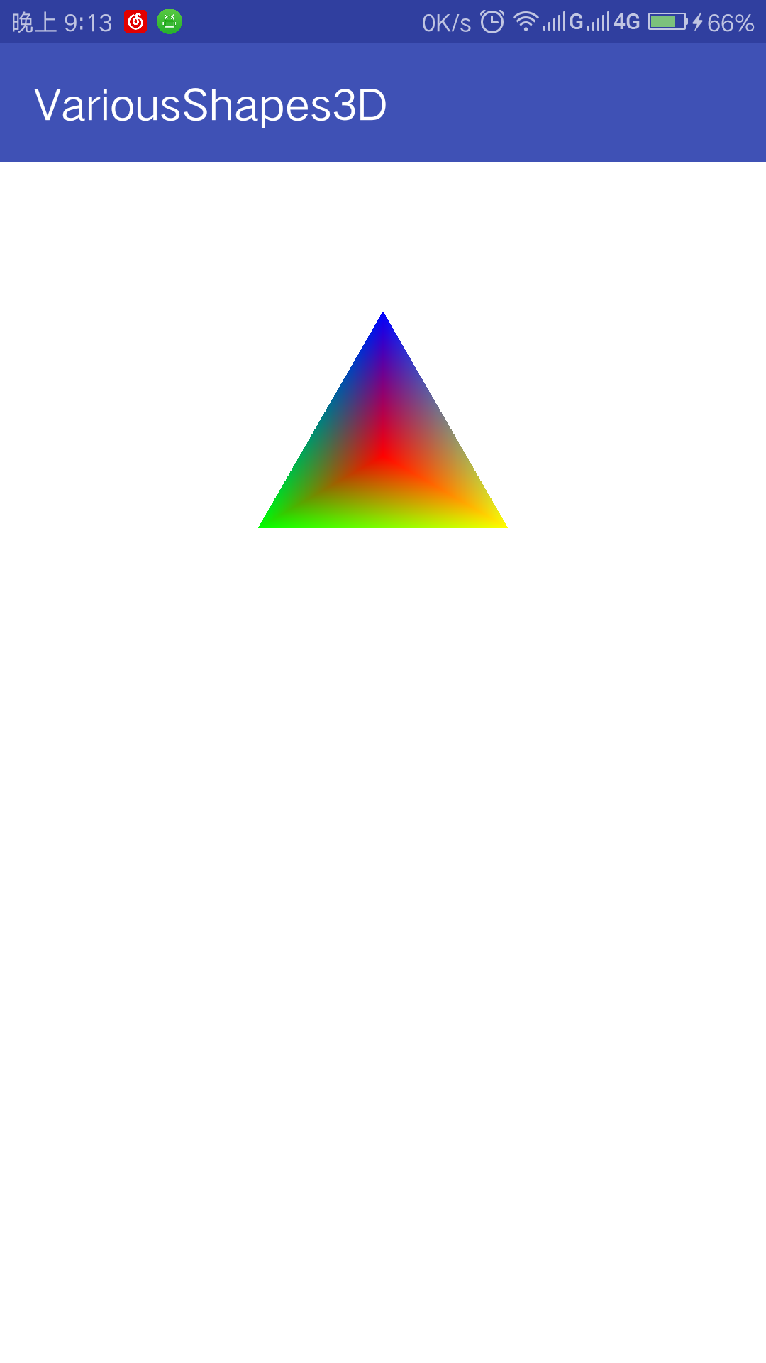
为了让应用显示正四面体我们还得更新下MainActivity.onCreate的代码如下
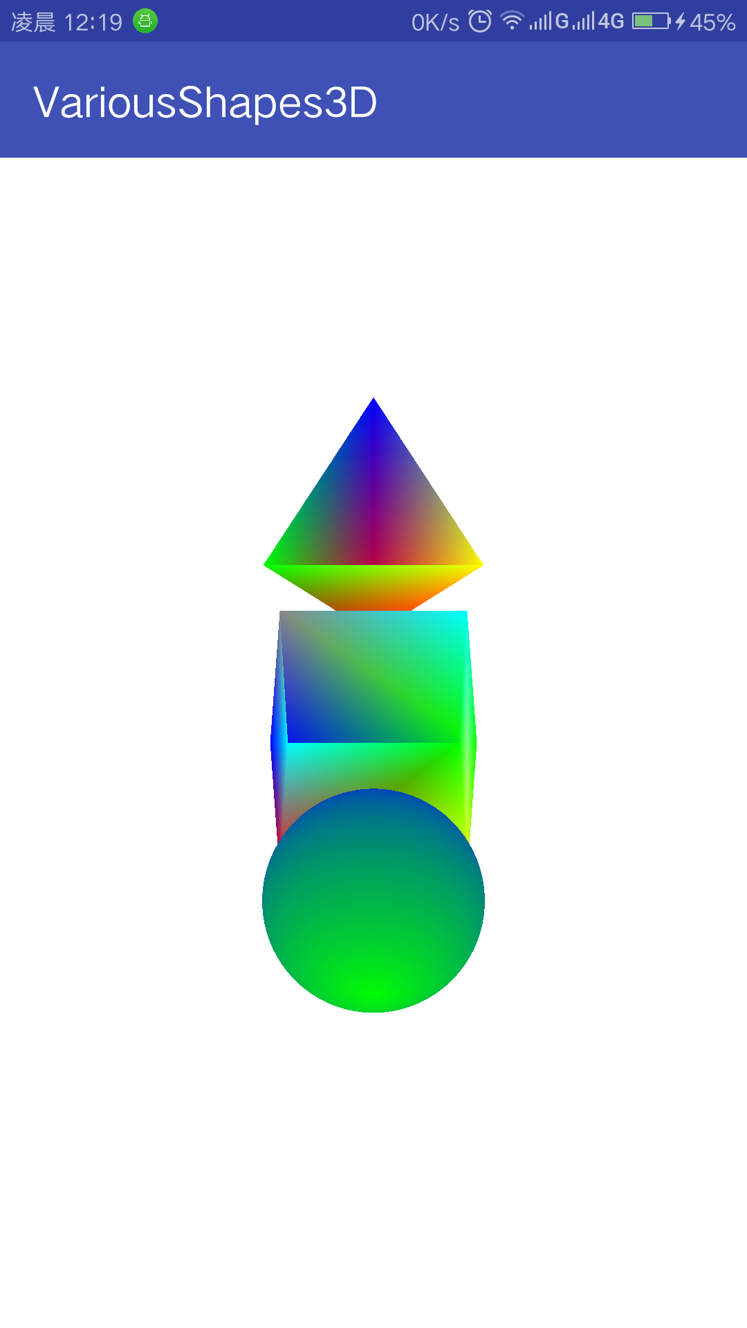
@Overrideprotected void onCreate(Bundle savedInstanceState) {super.onCreate(savedInstanceState);//2,创建GLSurfaceView对象glSurfaceView = new GLSurfaceView(this);//3,设置OpenGL ES版本为2.0glSurfaceView.setEGLContextClientVersion(2);//4,设置渲染器MyRenderer renderer = new MyRenderer(this);glSurfaceView.setRenderer(renderer);//添加ProgramShapeProgram program = new ShapeProgram();program.addShape(new Tetrahedron(new Point(0f, 0.8f, 0f), 0.4f));renderer.addProgram(program);//5,设置GLSurfaceView为主窗口setContentView(glSurfaceView);}运行程序,会得到如下效果
创建正方体
在shapes包下添加Cube类如下
package com.yxf.variousshapes3d.shapes;import android.graphics.Color;import com.yxf.variousshapes3d.Point;import java.nio.ByteBuffer;
import java.nio.FloatBuffer;import static android.opengl.GLES20.GL_TRIANGLES;
import static android.opengl.GLES20.GL_UNSIGNED_BYTE;
import static android.opengl.GLES20.glDrawElements;public class Cube extends BaseShape {private float[] vertices;private FloatBuffer vertexData;private float size;private int coordinateCount;private ByteBuffer positionBuffer;public Cube(Point center, float size) {super(center);vertices = new float[(COLOR_COMPONENT_COUNT + POSITION_COMPONENT_COUNT) * 8];this.size = size;//绘制时所需顶点个数coordinateCount = 3 * 2 * 6;}@Overridepublic void initWithoutLock() {float len = size / 2;int color;int i = 0;//顶面正方形左上角,0vertices[i++] = center.x - len;vertices[i++] = center.y + len;vertices[i++] = center.z + len;color = Color.BLUE;vertices[i++] = Color.red(color) / 255f;vertices[i++] = Color.green(color) / 255f;vertices[i++] = Color.blue(color) / 255f;vertices[i++] = Color.alpha(color) / 255f;//顶面正方形左下角,1vertices[i++] = center.x - len;vertices[i++] = center.y - len;vertices[i++] = center.z + len;color = Color.RED;vertices[i++] = Color.red(color) / 255f;vertices[i++] = Color.green(color) / 255f;vertices[i++] = Color.blue(color) / 255f;vertices[i++] = Color.alpha(color) / 255f;//顶面正方形右下角,2vertices[i++] = center.x + len;vertices[i++] = center.y - len;vertices[i++] = center.z + len;color = Color.YELLOW;vertices[i++] = Color.red(color) / 255f;vertices[i++] = Color.green(color) / 255f;vertices[i++] = Color.blue(color) / 255f;vertices[i++] = Color.alpha(color) / 255f;//顶面正方形右上角,3vertices[i++] = center.x + len;vertices[i++] = center.y + len;vertices[i++] = center.z + len;color = Color.GREEN;vertices[i++] = Color.red(color) / 255f;vertices[i++] = Color.green(color) / 255f;vertices[i++] = Color.blue(color) / 255f;vertices[i++] = Color.alpha(color) / 255f;//底面正方形左上角,4vertices[i++] = center.x - len;vertices[i++] = center.y + len;vertices[i++] = center.z - len;color = Color.GRAY;vertices[i++] = Color.red(color) / 255f;vertices[i++] = Color.green(color) / 255f;vertices[i++] = Color.blue(color) / 255f;vertices[i++] = Color.alpha(color) / 255f;//底面正方形左下角,5vertices[i++] = center.x - len;vertices[i++] = center.y - len;vertices[i++] = center.z - len;color = Color.CYAN;vertices[i++] = Color.red(color) / 255f;vertices[i++] = Color.green(color) / 255f;vertices[i++] = Color.blue(color) / 255f;vertices[i++] = Color.alpha(color) / 255f;//底面正方形右下角,6vertices[i++] = center.x + len;vertices[i++] = center.y - len;vertices[i++] = center.z - len;color = Color.GREEN;vertices[i++] = Color.red(color) / 255f;vertices[i++] = Color.green(color) / 255f;vertices[i++] = Color.blue(color) / 255f;vertices[i++] = Color.alpha(color) / 255f;//底面正方形右上角,7vertices[i++] = center.x + len;vertices[i++] = center.y + len;vertices[i++] = center.z - len;color = Color.CYAN;vertices[i++] = Color.red(color) / 255f;vertices[i++] = Color.green(color) / 255f;vertices[i++] = Color.blue(color) / 255f;vertices[i++] = Color.alpha(color) / 255f;vertexData = encodeVertices(vertices);positionBuffer = ByteBuffer.allocateDirect(coordinateCount).put(new byte[]{//顶正方形0, 1, 2,0, 2, 3,//底正方形7, 6, 5,7, 5, 4,//前正方形1, 5, 6,1, 6, 2,//后正方形3, 7, 4,3, 4, 0,//左正方形0, 4, 5,0, 5, 1,//右正方形2, 6, 7,2, 7, 3,});positionBuffer.position(0);}@Overrideprotected FloatBuffer getVertexData() {return vertexData;}@Overrideprotected void drawArrays() {glDrawElements(GL_TRIANGLES, coordinateCount, GL_UNSIGNED_BYTE, positionBuffer);}@Overrideprotected void preDraw() {}@Overrideprotected void afterDraw() {}
}
绘制过程和绘制正四面体几乎一致便不再解释
在MainActivity,onCreate()中添加如下代码
program.addShape(new Cube(new Point(0f, 0f, 0f), 0.6f));运行程序会获得如下效果
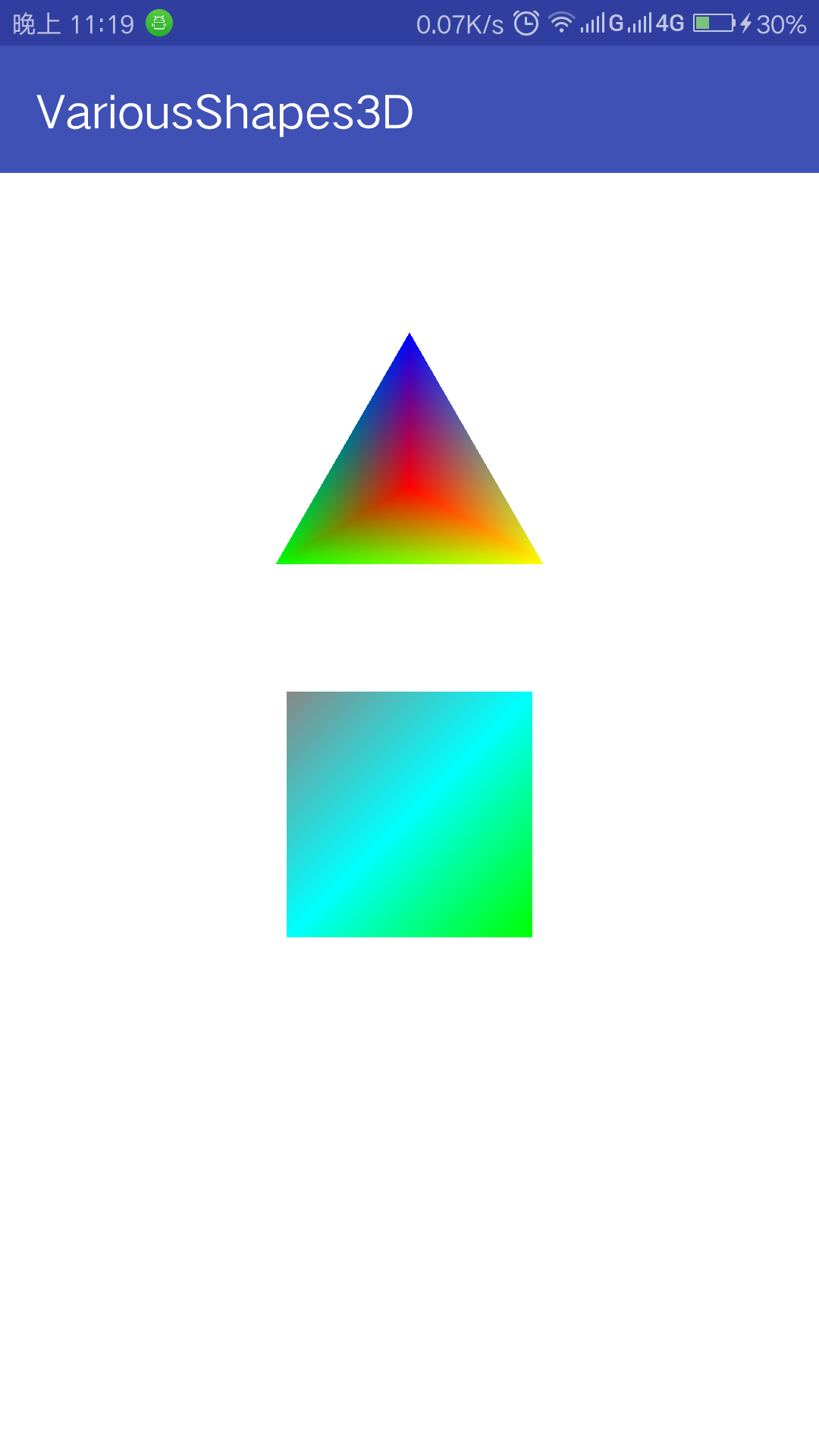
然而绘制的是正方体,看起来却是正方形,根本没有立体感可言,如何处理这个问题,我们先放一放,等绘制完球体再讨论
创建球形
在shapes包下添加Ball类如下
package com.yxf.variousshapes3d.shapes;import android.graphics.Color;import com.yxf.variousshapes3d.Point;import java.nio.FloatBuffer;import static android.opengl.GLES20.GL_TRIANGLE_STRIP;
import static android.opengl.GLES20.glDrawArrays;public class Ball extends BaseShape {private float radius;private int circleCount;private float angleStep;private float[] vertices;private FloatBuffer vertexData;private final int bottomColor = Color.BLUE;private final int topColor = Color.GREEN;private int pointCount = 0;public Ball(Point center, float radius, int circleCount) {super(center);this.radius = radius;this.circleCount = circleCount;angleStep = (float) (Math.PI * 2 / circleCount);}@Overridepublic void initWithoutLock() {int br = Color.red(bottomColor);int bg = Color.green(bottomColor);int bb = Color.blue(bottomColor);int ba = Color.alpha(bottomColor);int tr = Color.red(topColor);int tg = Color.green(topColor);int tb = Color.blue(topColor);int ta = Color.alpha(topColor);int zCount = circleCount / 2 + 1;int cCount = circleCount + 1;int len = POSITION_COMPONENT_COUNT + COLOR_COMPONENT_COUNT;pointCount = zCount * cCount * 2;vertices = new float[len * pointCount];int i = 0;for (int k = 0; k < zCount; k++) {float zAngle = (float) (-Math.PI / 2 + k * angleStep);float r = (float) (radius * Math.cos(zAngle));for (int j = 0; j < cCount; j++) {int index;if (k == 0) {index = i / len;vertices[i++] = center.x;vertices[i++] = center.y;vertices[i++] = center.z - radius;vertices[i++] = br;vertices[i++] = bg;vertices[i++] = bb;vertices[i++] = ba;i += len;} else {index = i / len;vertices[i++] = center.x + (float) (r * Math.cos(j * angleStep));vertices[i++] = center.y + (float) (r * Math.sin(j * angleStep));vertices[i++] = center.z + (float) (radius * Math.sin(zAngle));vertices[i++] = getMixtureColor(br, tr, index, pointCount);vertices[i++] = getMixtureColor(bg, tg, index, pointCount);vertices[i++] = getMixtureColor(bb, tb, index, pointCount);vertices[i++] = getMixtureColor(ba, ta, index, pointCount);int strip = len * 2 * cCount;int t = i - len;vertices[i++ - strip] = vertices[t++];vertices[i++ - strip] = vertices[t++];vertices[i++ - strip] = vertices[t++];vertices[i++ - strip] = vertices[t++];vertices[i++ - strip] = vertices[t++];vertices[i++ - strip] = vertices[t++];vertices[i++ - strip] = vertices[t++];}}}vertexData = encodeVertices(vertices);}private float getMixtureColor(int firstColor, int secondColor, int index, int count) {return (firstColor + (secondColor - firstColor) * index / count) / 255f;}@Overrideprotected FloatBuffer getVertexData() {return vertexData;}@Overrideprotected void drawArrays() {glDrawArrays(GL_TRIANGLE_STRIP, 0, pointCount);}@Overrideprotected void preDraw() {}@Overrideprotected void afterDraw() {}
}
这次的绘制我们没有再使用glDrawElements(),而是使用回了glDrawArrays(),并且用了GL_TRIANGLE_STRIP属性,这个也在之前博客中讲过,故而不再赘述,参见Android OpenGL ES 部分方法说明 – glDrawArrays
绘制过程则是采用从球底部到顶部一圈一圈绘制的方式绘制的,由于底部和顶部的小圈也用了和中间一样那么多的顶点来绘制,故而感觉性能并没有达到最佳.在这里只做简单的示例,有兴趣的同学可以自己尝试考虑让绘制顶点数随着接近上下两端而减小,以获得更好的性能.
然后在MainActivity,onCreate()中添加如下代码
program.addShape(new Ball(new Point(0f, -0.8f, 0f), 0.6f));运行程序会获得如下效果
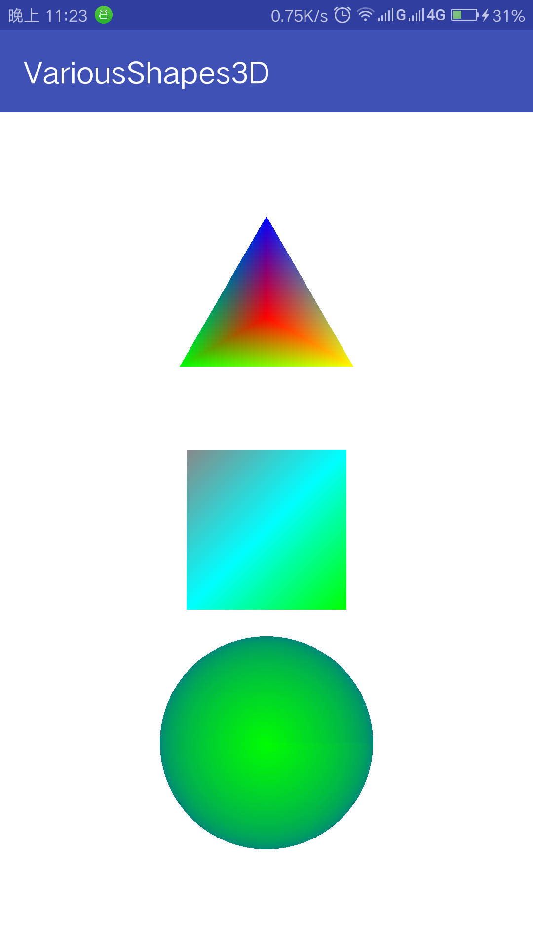
这个球立体感也不强,那么接下来我们正式来解决这个问题吧
引入透视投影
之前我们使用的是正交投影,正交投影的属性是无论距离远近,大小都一样,而正交投影也大多数时间是用于二维的
接下来我们将建立透视投影,透视投影是近大远小的,完全相同的两个物体,不同的距离,两物体所有相同点的连线都将交于一点.
首先在CommonUtils类中添加如下方法
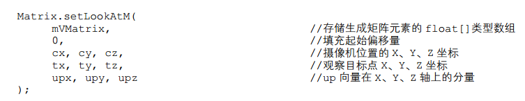
public static void perspectiveM(float[] m, float yFovInDegrees, float aspect, float n, float f) {final float angleInRadians = (float) (yFovInDegrees * Math.PI / 180.0);final float a = (float) (1.0 / Math.tan(angleInRadians / 2.0));int i = 0;m[i++] = a / aspect;m[i++] = 0f;m[i++] = 0f;m[i++] = 0f;m[i++] = 0f;m[i++] = a;m[i++] = 0f;m[i++] = 0f;m[i++] = 0f;m[i++] = 0f;m[i++] = -((f + n) / (f - n));m[i++] = -1f;m[i++] = 0f;m[i++] = 0f;m[i++] = -(2f * f * n) / (f - n);m[i++] = 0f;}此方法用于创建一个透视投影矩阵
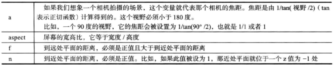
方法参数说明如下
在ShapeProgram头部增加两个全局变量width和height
更新ShapeProgram.onSurfaceChanged()如下
@Overridepublic void onSurfaceChanged(int width, int height) {super.onSurfaceChanged(width, height);this.width = width;this.height = height;initProjectionMatrix();}在ShapeProgram头部加入modeMatrix的定义
private final float[] modeMatrix = new float[16]; private void initProjectionMatrix() {synchronized (mMatrixLock) {//构建透视投影矩阵CommonUtils.perspectiveM(projectionMatrix, 45, (float) width/ (float) height, 1f, 10f);//重置模型矩阵setIdentityM(modeMatrix, 0);//设置相机位置setLookAtM(modeMatrix, 0, 0f, 1.2f, 2.2f, 0f, 0f, 0f, 0f, 1f, 0f);//将模型矩阵和透视投影矩阵相乘获得新的投影矩阵final float[] temp = new float[16];multiplyMM(temp, 0, projectionMatrix, 0, modeMatrix, 0);System.arraycopy(temp, 0, projectionMatrix, 0, temp.length);}}上诉方法中引入了一个新的矩阵处理方法setLookAtm,
这个方法是用来设置观察者的位置和视觉方向的,可以将其认为是摄像机,其方法参数说明如下
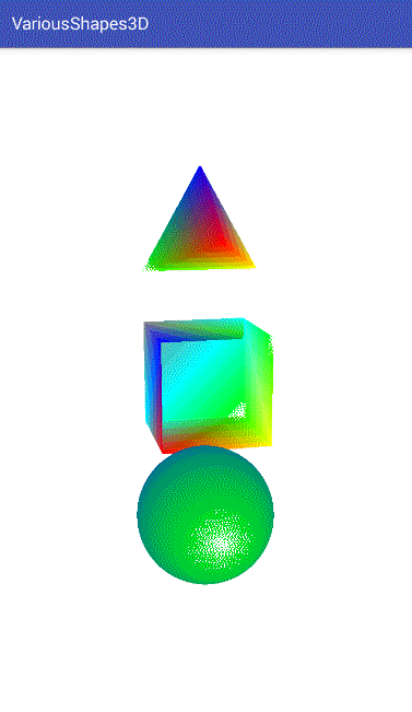
运行程序会获得如下效果
增加触摸事件
现在我们有3D效果了,但是却还没有全貌
我们再加入触摸事件,让我们可以通过滑动来旋转图形以观察全貌
在ShapeProgram类头部添加rotateX,rotateY,rotateZ来记录旋转值.
加入
private Object mMatrixLock = new Object();来控制矩阵的数据和旋转角同步
然后在ShapeProgram中添加如下方法
public void rotate(float x, float y, float z) {synchronized (mMatrixLock) {rotateX += x;rotateY += y;rotateZ += z;}}
并修改ShapeProgram.onPreDraw()方法如下
@Overridepublic void prepareDraw(int program) {synchronized (mMatrixLock) {initProjectionMatrix();setIdentityM(modeMatrix, 0);rotateM(modeMatrix, 0, rotateX, 1f, 0f, 0f);rotateM(modeMatrix, 0, rotateY, 0f, 1f, 0f);rotateM(modeMatrix, 0, rotateZ, 0f, 0f, 1f);float[] temp = new float[16];multiplyMM(temp, 0, projectionMatrix, 0, modeMatrix, 0);System.arraycopy(temp, 0, projectionMatrix, 0, temp.length);Log.d("VariousShapes", "x ; " + rotateX + " , y : " + rotateY);glUniformMatrix4fv(uMatrixLocation, 1, false, projectionMatrix, 0);}}这样我们的ShapeProgram就具备了旋转功能
然后修改MainActivity,在onCreate最后添加如下代码
glSurfaceView.setOnTouchListener(new View.OnTouchListener() {@Overridepublic boolean onTouch(View v, MotionEvent event) {switch (event.getAction()) {case MotionEvent.ACTION_DOWN:lastX = (int) event.getX();lastY = (int) event.getY();break;case MotionEvent.ACTION_MOVE:int x = (int) event.getX();int y = (int) event.getY();int dx = x - lastX;int dy = y - lastY;lastX = x;lastY = y;program.rotate(dy / 10f,dx / 10f, 0f);break;}return true;}});运行程序,便可以通过滑动控制旋转图形了
但是会发现有个缺点,我们颜色明明不是透明的,但是却可以看到对面背部的颜色,这是非常影响视觉效果的,那么该如何处理呢?
背面裁剪
通过背面裁剪的方式我们可以将背对相机的颜色影藏掉
在MyRender.onCreate()中添加如下代码
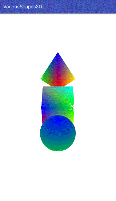
glEnable(GL_CULL_FACE);运行程序获得效果如图
卷绕
然而细心一点又会发现,上面正四面体旋转后消失了
这是为什么呢?
原来在我们启用背面裁剪时,OpenGL也是会根据是否顺时针绘制还是逆时针绘制来判断绘制哪面.
默认绘制点连线程逆时针的那一面.
这说明我们上面代码中的正四面体是存在顺时针的点的.
查看代码确实,在positionBuffer中,定义了一组0,1,2的点是顺时针的.
修改positionBuffer的值如下
positionBuffer = ByteBuffer.allocateDirect(coordinateCount).put(new byte[]{0, 2, 1,0, 1, 3,2, 0, 3,1, 2, 3,});将0,1,2改成0,2,1后再运行下应该就没有上面的问题了.
示例源码
OpenGL-VariousShapes3D
参考
OpenGL ES应用开发实践指南 Android卷
相关链接
OpenGL ES 中 GLSL Shader常见属性说明
Android OpenGL ES 部分方法说明
OpenGL ES初探(一) – 用OpenGL画一个三角形(1)
OpenGL ES初探(三) – 用OpenGL画正方形,圆,正多边形,圆环,正五角星
附录
最初的源码
附1
MainActivity.java
package com.yxf.variousshapes;import android.opengl.GLSurfaceView;
import android.os.Bundle;
import android.support.v7.app.AppCompatActivity;public class MainActivity extends AppCompatActivity {//1,定义GLSurfaceView对象,这个View提供了OpenGL ES的显示窗口private GLSurfaceView glSurfaceView;@Overrideprotected void onCreate(Bundle savedInstanceState) {super.onCreate(savedInstanceState);//2,创建GLSurfaceView对象glSurfaceView = new GLSurfaceView(this);//3,设置OpenGL ES版本为2.0glSurfaceView.setEGLContextClientVersion(2);//4,设置渲染器glSurfaceView.setRenderer(new MyRenderer(this));//5,设置GLSurfaceView为主窗口setContentView(glSurfaceView);}@Overrideprotected void onPause() {super.onPause();//6.1,当Activity暂停时暂停glSurfaceViewglSurfaceView.onPause();}@Overrideprotected void onResume() {super.onResume();//6.2,当Activity恢复时恢复glSurfaceViewglSurfaceView.onResume();}
}
附2
CommonUtils.java
package com.yxf.variousshapes;import android.content.Context;
import android.util.Log;import java.io.BufferedReader;
import java.io.IOException;
import java.io.InputStream;
import java.io.InputStreamReader;import static android.opengl.GLES20.GL_COMPILE_STATUS;
import static android.opengl.GLES20.GL_FRAGMENT_SHADER;
import static android.opengl.GLES20.GL_LINK_STATUS;
import static android.opengl.GLES20.GL_VERTEX_SHADER;
import static android.opengl.GLES20.glAttachShader;
import static android.opengl.GLES20.glCompileShader;
import static android.opengl.GLES20.glCreateProgram;
import static android.opengl.GLES20.glCreateShader;
import static android.opengl.GLES20.glGetProgramInfoLog;
import static android.opengl.GLES20.glGetProgramiv;
import static android.opengl.GLES20.glGetShaderInfoLog;
import static android.opengl.GLES20.glGetShaderiv;
import static android.opengl.GLES20.glLinkProgram;
import static android.opengl.GLES20.glShaderSource;//1,静态导入导入OpenGL ES 2.0常用方法public class CommonUtils {private static final String TAG = "CommonUtils";/*** 用于读取GLSL Shader文件内容** @param context* @param resId* @return*/public static String readTextFromResource(Context context, int resId) {StringBuilder builder = new StringBuilder();InputStream inputStream = null;InputStreamReader inputStreamReader = null;BufferedReader reader = null;try {inputStream = context.getResources().openRawResource(resId);inputStreamReader = new InputStreamReader(inputStream);reader = new BufferedReader(inputStreamReader);String nextLine;while ((nextLine = reader.readLine()) != null) {builder.append(nextLine);builder.append("\n");}} catch (IOException e) {e.printStackTrace();} finally {try {if (reader != null) {reader.close();}if (inputStreamReader != null) {inputStreamReader.close();}if (inputStream != null) {inputStream.close();}} catch (IOException e) {e.printStackTrace();}}return builder.toString();}/*** 编译着色器** @param type* @param source* @return*/public static int compileShader(int type, String source) {final int shaderId = glCreateShader(type);if (shaderId == 0) {//2,如果着色器创建失败则会返回0Log.w(TAG, "Could not create new shader");return 0;}//3,将Shader源文件加载进ID为shaderId的shader中glShaderSource(shaderId, source);//4,编译这个shaderglCompileShader(shaderId);final int[] status = new int[1];//5,获取编译状态储存于status[0]glGetShaderiv(shaderId, GL_COMPILE_STATUS, status, 0);Log.v(TAG, "compile source : \n" + source + "\n" +"info log : " + glGetShaderInfoLog(shaderId));if (status[0] == 0) {//6,检查状态是否正常,0为不正常Log.w(TAG, "Compilation of shader failed.");return 0;}return shaderId;}/*** 编译顶点着色器** @param source* @return*/public static int compileVertexShader(String source) {return compileShader(GL_VERTEX_SHADER, source);}/*** 编译片段着色器** @param source* @return*/public static int compileFragmentShader(String source) {return compileShader(GL_FRAGMENT_SHADER, source);}/*** 创建OpenGL对象,并添加着色器,返回OpenGL对象Id* @param vertexShaderId* @param fragmentShaderId* @return*/public static int linkProgram(int vertexShaderId, int fragmentShaderId) {//7,创建OpenGL对象final int programId = glCreateProgram();if (programId == 0) {Log.w(TAG, "Create OpenGL program failed");return 0;}//8,在program上附上着色器glAttachShader(programId, vertexShaderId);glAttachShader(programId, fragmentShaderId);//9,链接程序glLinkProgram(programId);final int[] status = new int[1];glGetProgramiv(programId, GL_LINK_STATUS, status, 0);Log.v(TAG, "Results of linking program : \n" + glGetProgramInfoLog(programId));if (status[0] == 0) {Log.w(TAG, "Link program failed");return 0;}return programId;}
}
附3
Point.java
package com.yxf.variousshapes;public class Point {public float x;public float y;public float z;public Point(float x, float y, float z) {this.x = x;this.y = y;this.z = z;}
}
附4
shape_vertex_shader.glsl
uniform mat4 u_Matrix;
attribute vec4 a_Position;
attribute vec4 a_Color;varying vec4 v_Color;
void main() {v_Color = a_Color;gl_Position = u_Matrix * a_Position;
}
shape_fragment_shader.glsl
precision mediump float;varying vec4 v_Color;void main(){gl_FragColor = v_Color;
}- 上篇博客OpenGL ES初探(三) – 用OpenGL画正方形,圆,圆环,正五角星的源码
OpenGL-VariousShapes ↩
这篇关于OpenGL ES初探(四) -- 用OpenGL画正四面体,正方体,球的文章就介绍到这儿,希望我们推荐的文章对编程师们有所帮助!