本文主要是介绍【openBCI系列】Cyton的数据格式,希望对大家解决编程问题提供一定的参考价值,需要的开发者们随着小编来一起学习吧!
文章目录
- 前言
- 一、Proprietary ("RFDuino") vs Standard Bluetooth(专有的("RFDuino")与标准蓝牙的比较)
- 二、Serial Setup(串行设置)
- 三、Startup
- Cyton Board
- 8bit Board (deprecated)
- Initiating Binary Transfer(启动二进制传输)
- Firmware Version 1.0.0 (2014 to Fall 2016)(固件版本1.0.0(2014年至2016年秋季))
- Firmware Version 2.0.0 (Fall 2016 to Now) 固件版本 2.0.0(2016 年秋季至今)
- Binary Format(二进制形式)
- Header
- EEG Data
- Aux Data(辅助数据)
- Firmware Version 1.0.0 (2014 to Fall 2016)(固件版本1.0.0(2014年至2016年秋季))
- Firmware Version 2.0.0 (Fall 2016 to Now):固件版本2.0.0(2016年秋季至今)
- Footer
- 24-Bit Signed Data Values(24位有符号的数据值)
- 16-Bit Signed Data Values(16位有符号的数据值)
- 32-Bit Unsigned Time Stamp(32位无符号时间戳)
- Interpreting the EEG Data(解释脑电图数据)
- 总结(针对导师项目)
- 启动二进制传输。
- 数据的形式
- Header
- EEG Data
- Aux Data(辅助数据)
- Footer
- 24-Bit Signed Data Values(24位有符号的数据值)
- 解释脑电图数据
前言
本文旨在总结官方文档(十六通道见原文)
官方文档
This discussion of the OpenBCI data format only applies to OpenBCI (2014-2016) and (Fall 2016). For OpenBCI Cyton, the OpenBCI board contains either a ChipKIT or ATmega microcontroller that can both be programmed through the Arduino IDE. The Cyton board has an on-board RFDuino radio module acting as a “Device”. The Cyton system includes a USB dongle for the PC, which acts as the RFDuino “Host”. The format of the OpenBCI data as seen on the PC is defined by a combination of the Arduino code on the Cyton board and of the RFDuino code running on the Host. So, if you don’t like the data format defined here, feel free to change it! For more info on the v2 firmware, see these Notes On Updating and Using v2.0.0 Cyton Firmware. There is also further information on controlling the OpenBCI Cyton on our OpenBCI Cyton SDK page
关于OpenBCI数据格式的讨论只适用于OpenBCI(2014-2016)和(2016年秋季)。对于OpenBCI Cyton,OpenBCI板包含一个ChipKIT或ATmega微控制器,都可以通过Arduino IDE进行编程。Cyton板有一个板载RFDuino无线电模块,作为 “设备”。Cyton系统包括一个用于PC的USB dongle,它充当RFDuino的 “主机”。在PC上看到的OpenBCI数据的格式是由Cyton板上的Arduino代码和在主机上运行的RFDuino代码共同定义的。
一、Proprietary (“RFDuino”) vs Standard Bluetooth(专有的(“RFDuino”)与标准蓝牙的比较)
OpenBCI Cyton uses RFDuino modules for its Bluetooth wireless connection. To achieve the highest data rates, OpenBCI supplies a RFDuino USB dongle that connects to the computer. When using this USB dongle, higher data rates can be achieved versus using a standard bluetooth 4.n BLE connection.
If you prefer to use a standard bluetooth connection (to a mobile phone, for instance), that software and data format has not yet been defined.
OpenBCI Cyton使用RFDuino模块进行蓝牙无线连接。为了实现最高的数据速率,OpenBCI提供了一个连接到计算机的RFDuino USB dongle。当使用这个USB dongle时,与使用标准蓝牙4.n BLE连接相比,可以实现更高的数据速率。
如果你喜欢使用标准的蓝牙连接(例如与手机的连接),该软件和数据格式还没有被定义。
二、Serial Setup(串行设置)
The RFDuino USB dongle (the RFDuino “Host”) is connected to an FTDI USB<>Serial converter configured to appear to the computer as if it is a standard serial port running at a rate of 115200 baud using the typical 8-N-1. It is possible to run at faster baud (FT231XQ-R on dongle tested up to 1Mbaud), but 115200 is required if you want to upload code to the target uC.
The RFDuino USB dongle (the RFDuino “Host”) 连接到FTDI USB<>串口转换器,配置为在计算机上显示为标准串口,使用典型的8-N-1以115200波特的速率运行。有可能以更快的波特运行(dongle的FT231XQ-R测试到1Mbaud),但如果你想向目标uC上传代码,115200是必需的。
三、Startup
Cyton Board
The chipKIT on our 32bit Board does not go through a reset cycle when its serial port is opened. Because of this, it’s possible to connect to the 32bit board and not know it’s state. In this case, the terminal or application should write a v to the serial port, which causes the system to reset its state to default values.
我们的32位板上的chipKIT在其串行端口被打开时不经过一个复位周期。正因为如此,有可能连接到32位板而不知道它的状态。在这种情况下,终端或应用程序应该向串行端口写入一个v,这将导致系统将其状态重置为默认值。
8bit Board (deprecated)
When the serial port for the dongle is opened by your PC, it will reset an 8bit Board. That’s because the DTR signal from FTDI is getting sent over air, and the ATmega is configured as an Arduino UNO. You will see the familiar blink of the pin 13 LED. After a second or so, you will see the OpenBCI board generate a few lines of ASCII text displaying the device IDs of the ADS1299 and Accelerometer ending in $ $ $. If you are writing client software for the PC, your software must expect an ASCII string on startup, and look for the $ $ $ to know it is ready to receive commands.
当你的电脑打开 dongle的串口时,它将重置一个8位板。这是因为FTDI的DTR信号是通过空气发送的,而ATmega被配置为Arduino UNO。你会看到熟悉的第13针LED灯的闪烁。一秒钟左右,你会看到OpenBCI板产生几行ASCII文本,显示ADS1299和加速器的设备ID,以 $ $ $ 结束。如果你正在为PC编写客户端软件,你的软件必须在启动时期待一个ASCII字符串,并寻找 $ $ $ 以知道它已准备好接收命令。
Initiating Binary Transfer(启动二进制传输)
Once the OpenBCI has initialized itself and sent the $ $ $ , it waits for commands. In other words, it sends no data until it is told to start sending data. To begin data transfer, transmit a single ASCII b. Once the b is received, continuous transfer of data in binary format will ensue. To turn off the fire hose, send an s.
一旦OpenBCI初始化了自己并发送了$ $ $,它就等待命令。换句话说,在被告知开始发送数据之前,它不发送任何数据。要开始数据传输,请发送一个ASCII b。一旦收到b,二进制格式的数据将连续传输。要关闭这个数据流,请发送一个s。
Firmware Version 1.0.0 (2014 to Fall 2016)(固件版本1.0.0(2014年至2016年秋季))
Both the Host and Device radios take notice of the b and s, and go into or out of streamingMode accordingly. That’s right, the radio modules on both the OpenBCI board and the Dongle have two states:
主机和设备无线电都会注意到b和s,并相应地进入或退出streamingMode。没错,OpenBCI板上的无线电模块和the Dongle都有两种状态:
!streamingData(没有数据流):
The radios appear to be a transparent UART betweeen the PC and target uC
Command characters need some delay before and after sending to pass from PC to target uC
1、无线电设备似乎是PC和目标uC之间的一个透明UART。
2、命令字符在发送前后需要一些延迟,以便从PC到目标uC之间传递。
streamingData(有数据流)
1、Device radio expects to get 31 bytes in each data packet from the uC
2、After 1 second of no transmission, or not getting 31 bytes in time, Device and Host will revert to !streamingData mode
3、Command characters can be sent from PC following timing protocol above
1、设备电台希望从uC的每个数据包中得到31个字节
2、在1秒内没有传输,或没有及时得到31个字节后,设备和主机将恢复到没有流数据模式。
3、命令字符可以按照上述定时协议从PC发送
Firmware Version 2.0.0 (Fall 2016 to Now) 固件版本 2.0.0(2016 年秋季至今)
There are no states in the new Device and Host radio code. However we had to introduce a packet format that must be followed when trying to send samples at 250Hz! You must send a one byte header then by 31 bytes of data (your choice), followed by where X is 0-F in hex. This X is carried through to the PC/Driver and is described towards the end of the next section.0x41 0xCX
在新的设备和主机无线电代码中没有任何状态。然而,我们不得不引入一个数据包格式,当试图以250Hz的频率发送样本时,必须遵循这个格式。你必须发送一个字节的头,然后是31个字节的数据(你的选择),然后是X为0-F的十六进制。这个X被带到PC/Driver,并在下一节末尾进行了描述。
Binary Format(二进制形式)
Each packet contains a header followed by a sample counter, followed by 8 ADS channel data, followed by the three axes values of the accelerometer, followed by a footer. The accelerometer data are optional, and don’t need to be sent with every packet when used. if unused, the bytes will read 0. This allows for user defined auxiliary data to be sent in the last six bytes before the footer. Also, there may be room for compressing more samples. Here are details on the format.
每个数据包包含一个头,然后是一个采样计数器,接着是8个ADS通道数据,然后是加速度计的三个轴值,最后是一个脚注。加速计数据是可选的,使用时不需要与每个数据包一起发送。如果未使用,字节将读作0。这允许用户定义的辅助数据在页脚前的最后六个字节中发送。另外,可能还有空间来压缩更多的样本。下面是关于格式的细节。
Header
Byte 1: 0xA0
Byte 2: Sample Number(样品编号)
EEG Data
Note: values are 24-bit signed, MSB first
注意:数值是24位有符号的,MSB在前
Bytes 3-5: Data value for EEG channel 1
Bytes 6-8: Data value for EEG channel 2
Bytes 9-11: Data value for EEG channel 3
Bytes 12-14: Data value for EEG channel 4
Bytes 15-17: Data value for EEG channel 5
Bytes 18-20: Data value for EEG channel 6
Bytes 21-23: Data value for EEG channel 6
Bytes 24-26: Data value for EEG channel 8
Aux Data(辅助数据)
Bytes 27-32: 6 bytes of data defined and parsed based on the Footer below
字节27-32:6个字节的数据,根据下面的页脚定义和解析
Firmware Version 1.0.0 (2014 to Fall 2016)(固件版本1.0.0(2014年至2016年秋季))
The following table is sorted by . Drivers should use the to determine how to parse the 6 bytes.
下表是按.NET排序的。驱动程序应使用来确定如何解析这6个字节。
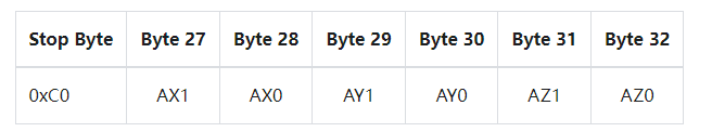
AX1-AX0: Data value for accelerometer channel X
AY1-AY0: Data value for accelerometer channel Y
AZ1-AZ0: Data value for accelerometer channel Z
AX1-AX0:加速度计通道X的数据值
AY1-AY0:加速度计通道Y的数据值
AZ1-AZ0:加速度计通道Z的数据值
Firmware Version 2.0.0 (Fall 2016 to Now):固件版本2.0.0(2016年秋季至今)
The following table is sorted by . Drivers should use the to determine how to parse the 6 bytes.
下表是按.NET排序的。驱动程序应使用来确定如何解析这6个字节。

We can still fit a 25Hz accelerometer in with time stamps due to some interlacing and timing constraints. Since we stream channel data at 250Hz and accelerometer at 25Hz; we have essentially 10 samples to send the accelerometer data in. When a or you should parse Byte 27 to indicate what Byte 28 is:0xC30xC4
由于一些隔行扫描和时间限制,我们仍然可以将25Hz的加速度计装入时间戳。由于我们以250Hz的速度传输通道数据,而加速度计以25Hz的速度传输;我们基本上有10个样本来发送加速度计的数据。当一个或你应该解析第27字节以表明第28字节是什么:0xC3,0xC4
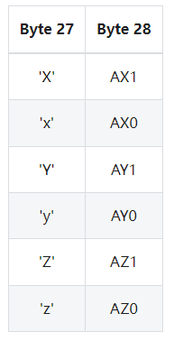
其中AC代表加速码,是一个ASCII字符。大写字母表示字节28是16位有符号整数的上8位,而小写字母表示16位有符号整数的下8位。你把这两个字节结合起来,形成一个数字。例如,假设一个样本进来时,AC等于’X’,我们就将AV中的值存储到一个临时变量中。下一个样本的AC字节为’x’,我们将把这个样本的28字节和上一个样本的28字节结合起来,然后按照下面16位有符号数据值一节所述进行转换。
T3-T0: 32 bit unsigned integer OpenBCI board time representing time since the board was started in ms. Simply store as an unsigned integer.
T3-T0: 32位无符号整数 OpenBCI板的时间,代表自板子启动以来的时间,单位为ms。简单地存储为一个无符号的整数。
0xC3 and are special in that they contain the same exact data as their counter parts and . However and are only sent after the time stamp/sync (<) command is issued from the PC/Driver to the Board. When the Board parses a < it sets a flag high to send on the next sample a different end byte to allow for the PC/Driver to calculate a round trip response time.0xC50xC40xC50xC30xC5
UDF stands for User Defined and for a general driver perspective, should be left alone and sent up to the user.
0xC3和0xC4是特殊的,因为它们所包含的数据与它们的对应部分完全相同。 然而,只有在PC/Driver向Board发出时间戳/同步(<)命令后才会发送。当电路板解析<时,它设置一个高电平标志,以便在下一次采样时发送一个不同的结束字节,使PC/Driver能够计算出往返的响应时间。
UDF代表用户定义,从一般驱动程序的角度来看,应该不受影响,由用户决定是否发送。
Footer
Byte 33: 0xCX where X is 0-F in hex
字节33:0xCX,其中X为0-F,以十六进制表示
24-Bit Signed Data Values(24位有符号的数据值)
For the EEG data values, you will note that we are transferring the data as a 24-bit signed integer, which is a bit unusual. We are using this number format because it is the native format used by the ADS1299 chip that is at the core of the Cyton board. To convert this unusual number format into a more standard 32-bit signed integer, you can steal some ideas from the example Processing (aka, Java) code:
对于脑电图的数据值,你会注意到我们是以24位有符号的整数来传输数据的,这有点不寻常。我们使用这种数字格式是因为它是作为Cyton板核心的ADS1299芯片所使用的本地格式。为了将这种不寻常的数字格式转换为更标准的32位有符号整数,你可以从Processing(又称Java)的示例代码中窃取一些想法。
int interpret24bitAsInt32(byte[] byteArray) {     int newInt = (  ((0xFF & byteArray[0]) <! 16) |  ((0xFF & byteArray[1]) <! 8) |   (0xFF & byteArray[2])  );  if ((newInt & 0x00800000) > 0) {  newInt |= 0xFF000000;  } else {  newInt &= 0x00FFFFFF;  }  return newInt;
}
16-Bit Signed Data Values(16位有符号的数据值)
The accelerometer data, if used, is sent as a 16bit signed value. We’re using a similar scheme to convert these values into 32bit integers in Processing.
加速计数据,如果使用的话,会以16位有符号的值发送。我们在Processing中使用类似的方案将这些值转换为32位整数。
int interpret16bitAsInt32(byte[] byteArray) {int newInt = (((0xFF & byteArray[0]) <! 8) |(0xFF & byteArray[1]));if ((newInt & 0x00008000) > 0) {newInt |= 0xFFFF0000;} else {newInt &= 0x0000FFFF;}return newInt;
32-Bit Unsigned Time Stamp(32位无符号时间戳)
To time stamp data, if used, is sent as a 32 bit unsigned integer representing time since the board was started in ms. We are using a different scheme to convert these values into 32 bit integers in Processing.
时间戳数据,如果使用的话,是以32位无符号整数的形式发送的,代表从板子开始的时间,单位是ms。我们在Processing中使用不同的方案将这些值转换为32位整数。
Interpreting the EEG Data(解释脑电图数据)
Once you receive and parse the data packets, it is important to know how to interpret the data so that the EEG values are useful in a quantitative way. The two critical pieces of information are (1) the sample rate and (2) the scale factor.
一旦你收到并解析了数据包,重要的是要知道如何解释数据,以便脑电图的数值能够以定量的方式发挥作用。两个关键信息是(1)采样率和(2)比例系数。
For the sample rate, we set the default rate to 250 Hz. Faster rates are supported by the ADS1299, but the RFDuino wireless link and the serial limits might not be able to keep up with faster sample rates. If you give it a try, let us know how it worked!
对于采样率,我们将默认速率设置为250 Hz。ADS1299支持更快的速率,但是RFDuino的无线链接和串行限制可能无法跟上更快的采样速率。如果你试一试,让我们知道它的效果如何!
For the scale factor, this is the multiplier that you use to convert the EEG values from “counts” (the int32 number that you parse from the binary stream) into scientific units like “volts”. By default, our Arduino sketch running on the OpenBCI board sets the ADS1299 chip to its maximum gain (24x), which results in a scale factor of 0.02235 microVolts per count. Because the gain is user-configurable (24x, 12x, 8x, 6x, 4x, 2x, 1x), the scale factor will be different. If the gain is changed, the equation that you should use for determining the scale factor is:
对于比例系数,这是你用来将EEG值从 “计数”(你从二进制流中解析出的int32数字)转换成科学单位(如 “伏特”)的乘数。默认情况下,我们在OpenBCI板上运行的Arduino草图将ADS1299芯片设置为其最大增益(24倍),这导致每计数的比例因子为0.02235微伏。因为增益是用户可配置的(24倍、12倍、8倍、6倍、4倍、2倍、1倍),所以比例因子会有所不同。如果改变了增益,你应该使用的确定比例系数的方程式是:
Scale Factor (Volts/count) = 4.5 Volts / gain / (2^23 - 1);Note that 2^23 might be an unexpected term in this equation considering that the ADS1299 is a 24-bit device. That’s because the 24bit raw count value is in 2’s complement format. This equation is from the ADS1299 data sheet, specifically it is from the text surrounding Table 7. This scale factor has also been confirmed experimentally using known calibration signals.
Accelerometer data must also be scaled before it can be correctly interpreted. The equation used to scale Accelerometer data is as follows (We assume 4Gs, so 2mG per digit):
请注意,考虑到ADS1299是一个24位的设备,2^23可能是这个方程中的一个意外项。这是因为24位的原始计数值是2的补码格式。这个方程来自ADS1299的数据表,特别是来自表7周围的文字。这个比例系数也已经用已知的校准信号在实验中得到确认。
加速计数据在正确解释之前也必须进行缩放。用于缩放加速器数据的公式如下(我们假设是4G,所以每一位数字为2mG)。
Accelerometer Scale Factor = 0.002 / 2^4;As of January 2021, these constants and equations are included in BrainFlow for Cyton users! This means users can pick any supported language and the data will already be scaled appropriately. These equations are still necessary if you plan to use data stored to SD card using a Cyton.
从2021年1月起,这些常数和方程都包含在BrainFlow中,供Cyton用户使用!这意味着用户可以选择任何支持的语言,并且数据已经被适当地缩放。这意味着用户可以选择任何支持的语言,并且数据已经被适当地缩放。如果你打算用Cyton使用存储在SD卡上的数据,这些方程仍然是必要的。
总结(针对导师项目)
项目所使用的是cycon。
官方文档
启动二进制传输。
在新的设备和主机无线电代码中没有任何状态。然而,我们不得不引入一个数据包格式,当试图以250Hz的频率发送样本时,必须遵循这个格式。你必须发送一个字节的头,然后是31个字节的数据(你的选择),然后是X为0-F的十六进制。这个X被带到PC/Driver,
数据的形式
每个数据包包含一个头,然后是一个采样计数器,接着是8个ADS通道数据,然后是加速度计的三个轴值,最后是一个脚注。加速计数据是可选的,使用时不需要与每个数据包一起发送。如果未使用,字节将读作0。这允许用户定义的辅助数据在页脚前的最后六个字节中发送。

注释:此图片为openBCI官方自带的标准化数据
Header
Byte 1: 0xA0
Byte 2: Sample Number(样品编号)
EEG Data
Note: values are 24-bit signed, MSB first
注意:数值是24位有符号的,MSB在前
Bytes 3-5: Data value for EEG channel 1
Bytes 6-8: Data value for EEG channel 2
Bytes 9-11: Data value for EEG channel 3
Bytes 12-14: Data value for EEG channel 4
Bytes 15-17: Data value for EEG channel 5
Bytes 18-20: Data value for EEG channel 6
Bytes 21-23: Data value for EEG channel 6
Bytes 24-26: Data value for EEG channel 8
Aux Data(辅助数据)
Bytes 27-32: 6 bytes of data defined and parsed based on the Footer below
字节27-32:6个字节的数据
AX1-AX0:加速度计通道X的数据值
AY1-AY0:加速度计通道Y的数据值
AZ1-AZ0:加速度计通道Z的数据值
Footer
字节33:0xCX,其中X为0-F,以十六进制表示

注:此为成员收集到的数据
24-Bit Signed Data Values(24位有符号的数据值)
For the EEG data values, you will note that we are transferring the data as a 24-bit signed integer, which is a bit unusual. We are using this number format because it is the native format used by the ADS1299 chip that is at the core of the Cyton board. To convert this unusual number format into a more standard 32-bit signed integer, you can steal some ideas from the example Processing (aka, Java) code:
对于脑电图的数据值,你会注意到我们是以24位有符号的整数来传输数据的,这有点不寻常。我们使用这种数字格式是因为它是作为Cyton板核心的ADS1299芯片所使用的本地格式。为了将这种不寻常的数字格式转换为更标准的32位有符号整数,你可以从Processing(又称Java)的示例代码中窃取一些想法。
int interpret24bitAsInt32(byte[] byteArray) {     int newInt = (  ((0xFF & byteArray[0]) <! 16) |  ((0xFF & byteArray[1]) <! 8) |   (0xFF & byteArray[2])  );  if ((newInt & 0x00800000) > 0) {  newInt |= 0xFF000000;  } else {  newInt &= 0x00FFFFFF;  }  return newInt;
}
解释脑电图数据
一旦你收到并解析了数据包,重要的是要知道如何解释数据,以便脑电图的数值能够以定量的方式发挥作用。两个关键信息是(1)采样率和(2)比例系数。
(1)对于采样率,我们将默认速率设置为250 Hz
(2)对于比例系数,这是你用来将EEG值从 “计数”(你从二进制流中解析出的int32数字)转换成科学单位(如 “伏特”)的乘数。默认情况下,我们在OpenBCI板上运行的Arduino草图将ADS1299芯片设置为其最大增益(24倍),这导致每计数的比例因子为0.02235微伏。因为增益是用户可配置的(24倍、12倍、8倍、6倍、4倍、2倍、1倍),所以比例因子会有所不同。如果改变了增益,你应该使用的确定比例系数的方程式是:
Scale Factor (Volts/count) = 4.5 Volts / gain / (2^23 - 1);这篇关于【openBCI系列】Cyton的数据格式的文章就介绍到这儿,希望我们推荐的文章对编程师们有所帮助!