本文主要是介绍VTK 数据处理:几何操作,希望对大家解决编程问题提供一定的参考价值,需要的开发者们随着小编来一起学习吧!
VTK 数据处理:几何操作
- VTK 数据处理:几何操作
- 实例 1:使用 vtkWarpTo 向指定点发生位移
- 实例 2:使用 vtkWarpVector 按照指定向量发生位移
- 实例 3:使用 vtkDeformPointSet 按照框架变形
VTK 数据处理:几何操作
VTK 的几何操作主要是让模型的点坐标发生偏移。
本文章主要介绍 3 种几何操作:
- 使用 vtkWarpTo 向指定点发生位移
- 使用 vtkWarpVector 按照指定向量发生位移
- 使用 vtkDeformPointSet 按照框架变形
实例 1:使用 vtkWarpTo 向指定点发生位移
vtkWarpTo 类可以设置点和比例,通过朝着该点弯曲来修改点坐标,用于将数据集中的点沿着指定向量进行位移。
#include "WarpTo.h"#include <vtkLineSource.h>
#include <vtkWarpTo.h>
#include <vtkTubeFilter.h>
#include <vtkPolyDataMapper.h>
#include <vtkActor.h>
#include <vtkRenderer.h>
#include <vtkRenderWindow.h>WarpTo::WarpTo(QWidget* parent) : QMainWindow(parent)
{ui.setupUi(this);_pVTKWidget = new QVTKOpenGLNativeWidget();this->setCentralWidget(_pVTKWidget);vtkNew<vtkRenderer> renderer;this->_pVTKWidget->renderWindow()->AddRenderer(renderer);this->_pVTKWidget->renderWindow()->Render();vtkNew<vtkLineSource> line;line->SetPoint1(0, 0, 0);line->SetPoint2(0, 1, 0);line->SetResolution(20);line->Update();vtkNew<vtkTubeFilter> tubeFilter;tubeFilter->SetInputConnection(line->GetOutputPort());tubeFilter->SetRadius(0.01);tubeFilter->SetNumberOfSides(50);tubeFilter->Update();vtkNew<vtkWarpTo> warpTo;warpTo->SetInputConnection(tubeFilter->GetOutputPort());warpTo->SetPosition(10, 1, 0);warpTo->SetScaleFactor(2.0);warpTo->AbsoluteOn();vtkNew<vtkPolyDataMapper> tubeMapper;tubeMapper->SetInputConnection(tubeFilter->GetOutputPort());vtkNew<vtkPolyDataMapper> warpToMapper;warpToMapper->SetInputConnection(warpTo->GetOutputPort());vtkNew<vtkActor> tubeActor;tubeActor->SetMapper(tubeMapper);vtkNew<vtkActor> warpToActor;warpToActor->SetMapper(warpToMapper);renderer->AddActor(tubeActor);renderer->AddActor(warpToActor);
}WarpTo::~WarpTo()
{
}
本实例中,我们创建了一个 vtkLineSource 类对象 line,设置它的起点和终点分别为 (0, 0, 0) 和 (0, 1, 0),并通过 vtkTubeFilter 将 line 变成一个圆柱。
创建一个 vtkWarpTo 类对象,设置点为 (10, 1, 0),偏转系数为 2。当AbsoluteOn设置为true时,位移是相对于数据集的原点进行的,这意味着所有的点都会向同一个方向偏移,即使它们在不同的位置上。但是,如果AbsoluteOn设置为false,则每个点的位移是相对于该点当前的位置进行计算的,这可能会导致每个点偏移到不同的方向,因此可能会产生非常不同的结果。
运行结果:

实例 2:使用 vtkWarpVector 按照指定向量发生位移
vtkWarpVector是VTK中的一个滤波器,用于根据向量数据对点进行位移。它将每个点的位置根据与该点相关联的向量进行调整,从而实现对数据集的形变操作。
该滤波器的作用是根据向量数据对点进行位移,可以用于创建各种效果,如流线、箭头、扭曲等。它可以用来可视化矢量场、流体运动、变形等应用场景。
使用vtkWarpVector滤波器时,需要提供一个向量数据集作为输入,这些向量表示了每个点的位移方向和大小。滤波器根据向量数据对每个点进行位移,从而改变其位置。位移的大小由向量的长度决定,位移的方向由向量的方向决定。
通过调整输入的向量数据,可以控制位移的强度和方向,从而实现各种不同的形变效果。这使得vtkWarpVector成为在可视化中展示矢量场和流体模拟等方面非常有用的工具。
#include "WarpVector.h"#include <vtkPoints.h>
#include <vtkNamedColors.h>
#include <vtkProperty.h>
#include <vtkCellArray.h>
#include <vtkLine.h>
#include <vtkDoubleArray.h>
#include <vtkPointData.h>
#include <vtkWarpVector.h>
#include <vtkPolyData.h>
#include <vtkPolyDataMapper.h>
#include <vtkActor.h>
#include <vtkRenderer.h>
#include <vtkRenderWindow.h>WarpVector::WarpVector(QWidget* parent)
{ui.setupUi(this);_pVTKWidget = new QVTKOpenGLNativeWidget();this->setCentralWidget(_pVTKWidget);vtkNew<vtkRenderer> renderer;this->_pVTKWidget->renderWindow()->AddRenderer(renderer);this->_pVTKWidget->renderWindow()->Render();vtkNew<vtkNamedColors> colors;vtkNew<vtkPoints> points;points->InsertNextPoint(0, 0, 0);points->InsertNextPoint(1, 0, 0);points->InsertNextPoint(2, 0, 0);points->InsertNextPoint(3, 0, 0);points->InsertNextPoint(4, 0, 0);vtkNew<vtkCellArray> lines;vtkNew<vtkLine> line;line->GetPointIds()->SetId(0, 0);line->GetPointIds()->SetId(1, 1);lines->InsertNextCell(line);line->GetPointIds()->SetId(0, 1);line->GetPointIds()->SetId(1, 2);lines->InsertNextCell(line);line->GetPointIds()->SetId(0, 2);line->GetPointIds()->SetId(1, 3);lines->InsertNextCell(line);line->GetPointIds()->SetId(0, 3);line->GetPointIds()->SetId(1, 4);lines->InsertNextCell(line);vtkNew<vtkPolyData> linePolyData;linePolyData->SetPoints(points);linePolyData->SetLines(lines);vtkNew<vtkDoubleArray> warpData;warpData->SetNumberOfComponents(3);warpData->SetName("warpData");double warp[] = { 0, 0, 0 };warp[1] = 0.0;warpData->InsertNextTuple(warp);warp[1] = 0.1;warpData->InsertNextTuple(warp);warp[1] = 0.5;warpData->InsertNextTuple(warp);warp[1] = 0.0;warpData->InsertNextTuple(warp);warp[1] = 0.3;warpData->InsertNextTuple(warp);linePolyData->GetPointData()->AddArray(warpData);linePolyData->GetPointData()->SetActiveVectors(warpData->GetName());vtkNew<vtkWarpVector> warpVector;warpVector->SetInputData(linePolyData);vtkNew<vtkPolyDataMapper> lineMapper;lineMapper->SetInputData(linePolyData);vtkNew<vtkPolyDataMapper> warpMapper;warpMapper->SetInputConnection(warpVector->GetOutputPort());vtkNew<vtkActor> lineActor;lineActor->SetMapper(lineMapper);vtkNew<vtkActor> warpActor;warpActor->SetMapper(warpMapper);warpActor->GetProperty()->SetColor(colors->GetColor3d("Gold").GetData());renderer->AddActor(lineActor);renderer->AddActor(warpActor);
}WarpVector::~WarpVector()
{
}
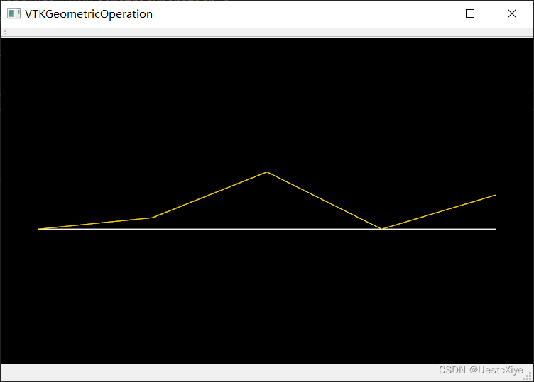
本实例首先创建了一个 vtkPoints 类对象 points,里面存储了 5 个点:(0, 0, 0)、(1, 0, 0)、(2, 0, 0)、(3, 0, 0)、(4, 0, 0)、(5, 0, 0)。接着创建了一个 vtkCellArray 类 line,里面存储了 前面 5 个点相邻两两连接的 4 条线段。最后用一个 linePolyData 类对象保存了 points 和 line。
创建一个 vtkDoubleArray 类对象 warpData,里面存储了 5 个向量数据:(0, 0, 0)、(0, 0.1, 0)、(0, 0.5, 0)、(0, 0, 0)、(0, 0.3, 0)。将这个数组添加到 linePolyData 中,并设为 ActiveVectors,之后使用 vtkWarpVector 类根据向量数据(刚刚设置的 warpData)对点进行位移。它将每个点的位置根据与该点相关联的向量进行调整,从而实现对数据集的形变操作。
运行结果:
实例 3:使用 vtkDeformPointSet 按照框架变形
vtkDeformPointSet 的主要作用是根据一组控制点和它们的位移,对输入的点集进行形变。该类通常用于实现基于物理模型或者仿真的点集形变,比如在有限元分析中用于模拟材料的变形行为。
使用vtkDeformPointSet,可以通过指定一组控制点和它们的位移来对输入的点集进行形变。控制点的位移可以通过外部计算得到,比如基于物理模型的仿真结果或者其他形变算法的计算结果。vtkDeformPointSet会根据这些位移信息,对输入的点集进行相应的形变操作,并输出形变后的点集。
这种形变操作可以用于模拟材料的变形、动态网格变形、动画效果等各种应用场景。通过调整控制点的位移,可以实现不同形式的形变效果,从而满足各种可视化和仿真需求。
#include "DeformPointSet.h"#include <vtkSphereSource.h>
#include <vtkPoints.h>
#include <vtkCellArray.h>
#include <vtkDeformPointSet.h>
#include <vtkPolyDataMapper.h>
#include <vtkActor.h>
#include <vtkRenderer.h>
#include <vtkRenderWindow.h>DeformPointSet::DeformPointSet(QWidget* parent) : QMainWindow(parent)
{ui.setupUi(this);_pVTKWidget = new QVTKOpenGLNativeWidget();this->setCentralWidget(_pVTKWidget);vtkNew<vtkRenderer> renderer;this->_pVTKWidget->renderWindow()->AddRenderer(renderer);this->_pVTKWidget->renderWindow()->Render();vtkNew<vtkSphereSource> sphere;sphere->SetThetaResolution(51);sphere->SetPhiResolution(17);sphere->Update();double bounds[6];sphere->GetOutput()->GetBounds(bounds);// 正八面体vtkNew<vtkPoints> points;points->SetNumberOfPoints(6);points->SetPoint(0, bounds[0] - 0.1 * (bounds[1] - bounds[0]), (bounds[2] + bounds[3]) / 2.0, (bounds[4] + bounds[5]) / 2.0);points->SetPoint(1, bounds[1] + 0.1 * (bounds[1] - bounds[0]), (bounds[2] + bounds[3]) / 2.0, (bounds[4] + bounds[5]) / 2.0);points->SetPoint(2, (bounds[1] + bounds[0]) / 2.0, bounds[2] - 0.1 * (bounds[3] - bounds[2]), (bounds[4] + bounds[5]) / 2.0);points->SetPoint(3, (bounds[1] + bounds[0]) / 2.0, bounds[3] + 0.1 * (bounds[3] - bounds[2]), (bounds[4] + bounds[5]) / 2.0);points->SetPoint(4, (bounds[1] + bounds[0]) / 2.0, (bounds[2] + bounds[3]) / 2.0, bounds[4] - 0.1 * (bounds[5] - bounds[4]));points->SetPoint(5, (bounds[1] + bounds[0]) / 2.0, (bounds[2] + bounds[3]) / 2.0, bounds[5] + 0.1 * (bounds[5] - bounds[4]));vtkNew<vtkCellArray> tris;tris->InsertNextCell(3);tris->InsertCellPoint(2); tris->InsertCellPoint(0); tris->InsertCellPoint(4);tris->InsertNextCell(3);tris->InsertCellPoint(1); tris->InsertCellPoint(2); tris->InsertCellPoint(4);tris->InsertNextCell(3);tris->InsertCellPoint(3); tris->InsertCellPoint(1); tris->InsertCellPoint(4);tris->InsertNextCell(3);tris->InsertCellPoint(0); tris->InsertCellPoint(3); tris->InsertCellPoint(4);tris->InsertNextCell(3);tris->InsertCellPoint(0); tris->InsertCellPoint(2); tris->InsertCellPoint(5);tris->InsertNextCell(3);tris->InsertCellPoint(2); tris->InsertCellPoint(1); tris->InsertCellPoint(5);tris->InsertNextCell(3);tris->InsertCellPoint(1); tris->InsertCellPoint(3); tris->InsertCellPoint(5);tris->InsertNextCell(3);tris->InsertCellPoint(3); tris->InsertCellPoint(0); tris->InsertCellPoint(5);vtkNew<vtkPolyData> regularOctahedronPolyData;regularOctahedronPolyData->SetPoints(points);regularOctahedronPolyData->SetPolys(tris);// vtkDeformPointSet 根据一组控制点和它们的位移,对输入的点集进行形变vtkNew<vtkDeformPointSet> deformPointSet;deformPointSet->SetInputConnection(sphere->GetOutputPort());deformPointSet->SetControlMeshData(regularOctahedronPolyData); // 把正八面体作为控制网格deformPointSet->Update();double controlPoint[3];points->GetPoint(5, controlPoint);points->SetPoint(5, controlPoint[0], controlPoint[1], bounds[5] + 0.8 * (bounds[5] - bounds[4]));points->Modified();vtkNew<vtkPolyDataMapper> deformedSphereMapper;deformedSphereMapper->SetInputConnection(deformPointSet->GetOutputPort());vtkNew<vtkPolyDataMapper> regularOctahedronMapper;regularOctahedronMapper->SetInputData(regularOctahedronPolyData);vtkNew<vtkActor> deformedSphereActor;deformedSphereActor->SetMapper(deformedSphereMapper);vtkNew<vtkActor> regularOctahedronActor;regularOctahedronActor->SetMapper(regularOctahedronMapper);renderer->AddActor(deformedSphereActor);renderer->AddActor(regularOctahedronActor);
}DeformPointSet::~DeformPointSet()
{
}
本实例创建了一个球体和一个正八面体。通过创建一个 vtkDeformPointSet 类,把球体作为输入,把正八面体作为控制网格。程序修改了正八面体的一个点的坐标,vtkDeformPointSet 类根据一组控制点(正八面体的点集)和它们的位移,对输入的点集(球体)进行形变。
运行结果:

这篇关于VTK 数据处理:几何操作的文章就介绍到这儿,希望我们推荐的文章对编程师们有所帮助!