本文主要是介绍Vector CANOE VT2516A配置详解,希望对大家解决编程问题提供一定的参考价值,需要的开发者们随着小编来一起学习吧!
Vector CANoe CAPL系列相关文章导览,下面链接可直接跳转
- CAPL入门到精通文章导览
Vector CANoe VT System系列板卡文章导览,下面链接可直接跳转
- Vector CANoe VT system传送门
文章目录
- 引言
- VT2516A FPGA
- 前后面板图
- Usage
- Basic Connection Scheme
- Connecting the ECU
- Signal Path Switching
- Bus Bars
- Measuring the Digital Input Signal
- Voltage Measurement
- Outputting a Digital Signal
- Load or Pull-up/down Resistor
- 接插件定义
- Technical Data VT2516A
- General
- Input Signals and Switches
- Digital Input
- PWM Measurement
- Voltage Measurement
- Digital Output
- PWM Generation
- CAPL实例
- VT System Configuration
- VT System Control
- CAPL函数库
- System Variables
- system-defined
- 创建variables
- 制作Panel
- 编写CAPL脚本
- 输出模式枚举
- 控制输出模式
- Go to PWM output mode
- Go to digital output mode
- Read value and display on the panel
- 项目实例
- 公众号
引言
本章节继续聊VT2516A数字板卡的功能,板卡详细内容见VT_System_Manual_EN.pdf,内容为个人理解,如有错误,欢迎指正
The Digital Module VT2516A is connected to up to 16 mainly digitally used inputs and outputs of an ECU. Mainly digitally used means that the signals have two states. In real in-vehicle operation actuators like signal lamps or sensors like switches are connected to these ECU I/Os.
The VT2516A provides several features to check the ECU behavior regarding these ECU inputs/outputs:
- For ECU output:
- Measurement of the digital ECU output signal (incl. PWM) and the ECU output voltage
- Simulation of the actuator load by an externally mounted load (e.g. a resistor)
- FOr ECU input:
- Sensor simulation by output of a digital or PWM signal with defined high/low level
- Sensor simulation by switching the ECU line to ECU ground or V b a t t V_{batt} Vbatt
- Relays to connect the ECU input or output to the original sensor or actuator
- Relays to generate electrical errors like disconnection of ECU lines (“open load, broken wire”)
好长一段内容,说的啥呢
- VT2516A板卡总共有16个数字型输入/输出通道,注意是单端信号
- 支持PWM测量和输入信号的电压测量
- 输出数字、PWM信号模拟传感器;将ECU引脚短接到地、电源模拟传感器。
- 通过继电器控制ECU输入输出,传感器和执行器的通断。
- 通过继电器制造电器故障,如断开负载,线路开路。
- 通过继电器接入真实负载/传感器
- 通过继电器接入模拟上拉或下拉电阻工况
VT2516A FPGA
手上暂时没有这个可编程板卡,等遇到了再补充
前后面板图
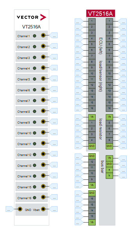
Usage
Basic Connection Scheme
Connecting the ECU
手册里面讲了很多典型应用场景
注意接线的时候是接在ECU侧的
Signal Path Switching

左侧对应ECU,中间是通过继电器切换的几种功能,右侧是可以实现的功能,如测量PWM、电压,输出电压,输出PWM。图很清晰,可以自己研究一下。
Bus Bars

由于是单端信号,line b通过一个继电器切换到 V b a t t V_{batt} Vbatt或者GND
Measuring the Digital Input Signal
测量数字输入信号
采样频率为50us,具体信号操作对应在CANoe中的系统变量,后面会介绍到。
Voltage Measurement
测量区间 -40V ~ +40V, 后面会介绍详细参数
测量电压信号,具体信号操作对应在CANoe中的系统变量,后面会介绍到。
Outputting a Digital Signal
输出数字信号,高低电平,PWM信号等,具体信号操作对应在CANoe中的系统变量,后面会介绍到。
Load or Pull-up/down Resistor
接入真实负载(如接个LED),模拟上拉或下拉电阻。
接插件定义
看手册5.4章节
Technical Data VT2516A
手册中都有,这里再贴一下
General

Input Signals and Switches
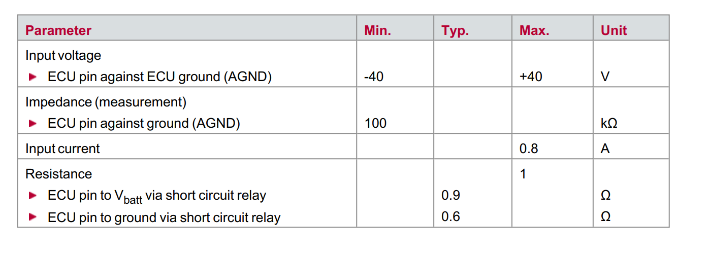
Digital Input

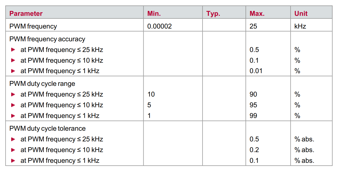
PWM Measurement

Voltage Measurement
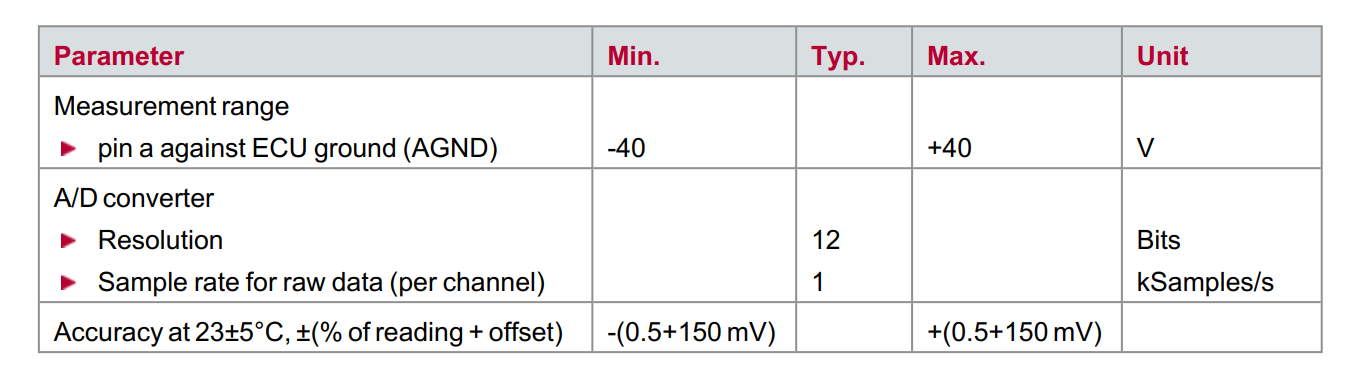
测量电压的精度取决于两个部分(值的百分比 + 偏移)
例如,如果测量电压为 -5 V,则精度为 ±175 mV(5V的 0.5 % + 150 mV)。
Digital Output

PWM Generation
CAPL实例
VT System Configuration
连接板卡,不知道咋操作的,看这里里面有详细说明

VT System Control
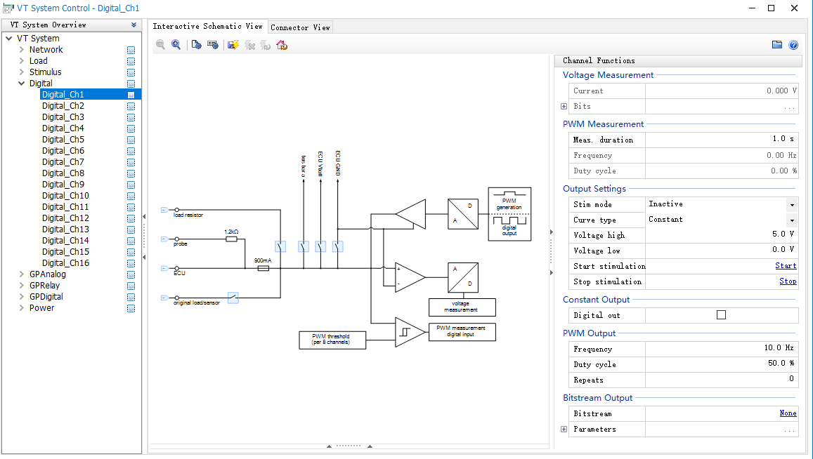
Output settings通过CAPL脚本来控制
CAPL函数库

(搜索这个文件CAPLfunctionsVTSystemOverview.htm,有详细介绍,包括函数使用示例等)
System Variables
system-defined

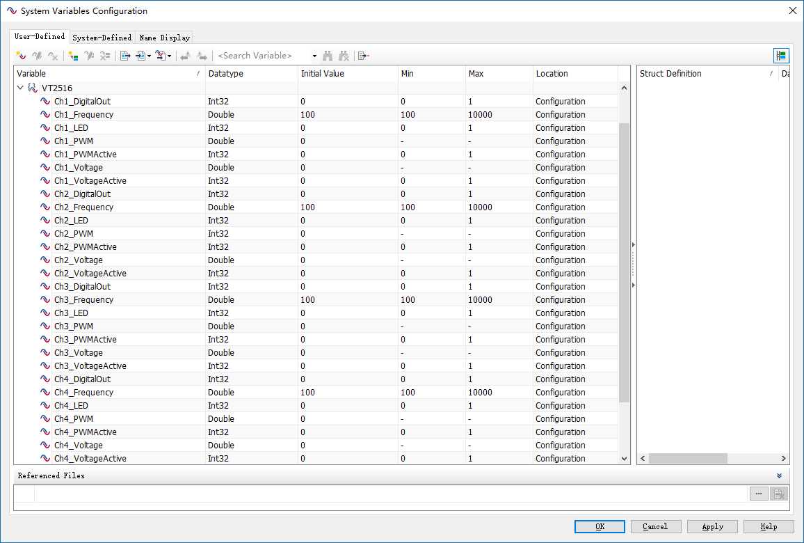
创建variables
根据需要创建如下variables以便于后续panel和capl进行调用
制作Panel

- 数字量电压输出
- PWM输出
- 电压采集
- PWM采集
编写CAPL脚本
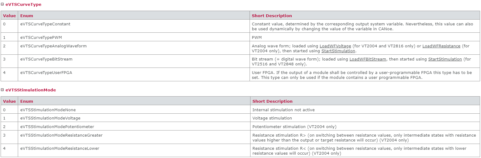
输出模式枚举
variables
{// Defines the modes in which each channel can beenum VT2516Modes { None, DigitalOut, PWMGenerator };// Stores the mode in which each channel isenum VT2516Modes VT2516Ch1Mode = None;enum VT2516Modes VT2516Ch2Mode = None;enum VT2516Modes VT2516Ch3Mode = None;enum VT2516Modes VT2516Ch4Mode = None;// Used to refresh measurement valuesmsTimer refreshTimer;
}
控制输出模式
switchModeVT2516 ( int channel, enum VT2516Modes mode )
{if( channel == 1 ){if( VT2516Ch1Mode != mode ){VT2516Ch1Mode = mode;if( mode == DigitalOut ){// Configure VT module channel as a digital output generator// See the CANoe help for detailssysvar::VTS::Digital_Ch1.SetPWMVoltageHigh (5.0);sysvar::VTS::Digital_Ch1.SetPWMVoltageLow (0.0);sysvar::VTS::Digital_Ch1.SetCurveType (0);sysvar::VTS::Digital_Ch1.SetStimulationMode (1);}else if( mode == PWMGenerator ){// Configure VT module channel as a PWM generator// See the CANoe help for detailssysvar::VTS::Digital_Ch1.StopStimulation();sysvar::VTS::Digital_Ch1.SetStimulationMode(1);sysvar::VTS::Digital_Ch1.SetCurveType(1);sysvar::VTS::Digital_Ch1.SetPWMVoltageLow(0.0);sysvar::VTS::Digital_Ch1.SetPWMVoltageHigh(5.0);sysvar::VTS::Digital_Ch1.SetPWMRepeats(0);sysvar::VTS::Digital_Ch1.StartStimulation();@sysvar::VTS::Digital_Ch1::PWMOutputDC = 40;@sysvar::VT2516::Ch1_DigitalOut = 0;}//end if}//end if}else if (channel == 2){// add code ...}
}
Go to PWM output mode
on sysvar sysvar::VT2516::Ch1_Frequency
{// Enable PWM@sysvar::VT2516::Ch1_PWMActive = 1;// Go to PWM output mode on this channel (switchMode function handles the VT configuration change)switchModeVT2516( 1, PWMGenerator );// Send setting from the panel to the VT module@sysvar::VTS::Digital_Ch1::PWMOutputFreq  = @sysvar::VT2516::Ch1_Frequency;
}// Enable PWM
on sysvar sysvar::VT2516::Ch1_PWMActive
{if( @sysvar::VT2516::Ch1_PWMActive == 1 ){switchModeVT2516( 1, None );switchModeVT2516( 1, PWMGenerator );}elsesysvar::VTS::Digital_Ch1.StopStimulation();
}
Go to digital output mode
on sysvar sysvar::VT2516::Ch1_DigitalOut
{// Go to digital output mode on this channel (switchMode function handles the VT configuration change)switchModeVT2516( 1, DigitalOut );// Send setting from the panel to the VT module@sysvar::VTS::Digital_Ch1::DigitalOutput  = @sysvar::VT2516::Ch1_DigitalOut;// Disable PWM@sysvar::VT2516::Ch1_PWMActive = 0;
}
Read value and display on the panel
在timer里面调用或者根据需要采用其他方式
void readValueFromVT2516()
{/* Read the current voltage value and store it in the// corresponding system variable to display it in the panel.*/@sysvar::VT2516::Ch1_Voltage = @sysvar::VTS::Digital_Ch1::Cur;/* Read the current frequency value and store it in the// corresponding system variable to display it in the panel.*/@sysvar::VT2516::Ch1_PWM = @sysvar::VTS::Digital_Ch1::PWMFreq;// add code ...
}
编译返回canoe主界面测试,在测试前请先确认接线!!!
项目实例
根据实际工况进行处理,不外乎上面的几种情况,只是和具体项目上的信号功能对应,有些可能是急停信号,碰撞信号,高压互锁输入,高压互锁输出,U/V/W三相PWM等等,如有问题,请关注,点赞,收藏,后台私信~~~
当前使用场景也比较单一,文中可能有部分内容未提及,或有误,请指出,谢谢!
公众号
欢迎关注公众号,加入专业技术交流。

这篇关于Vector CANOE VT2516A配置详解的文章就介绍到这儿,希望我们推荐的文章对编程师们有所帮助!