本文主要是介绍u-boot支持LCD显示(基于TQ2440),希望对大家解决编程问题提供一定的参考价值,需要的开发者们随着小编来一起学习吧!
平台简介
Linux版本:Linux-3.14
u-boot版本:u-boot-2015.04
硬件:TQ2440(内存:64MB NandFlash:256MB)
作者:彭东林
邮箱:pengdonglin137@163.com
摘要
这个版本的u-boot支持LCD很容易,期间,参考了tq2440官方u-boot中的LCD驱动。我们只需要在配置文件中配置相应的宏,实现LCD的初始化和使能函数即可。
代码我已经上传到CSDN上了,git@code.csdn.net:pengdonglin137/u-boot.git
其中一共有两个分支,一个是master分支,用于跟踪u-boot的最近分支,另一个是u-boot-2015-04-tq2440-spl分支,从名称上可以看到,这个分支的u-boot版本是u-boot-2015.04,用于向tq2440上移植。
使用方法:
git clone git@code.csdn.net:pengdonglin137/u-boot.git -b u-boot-2015-04-tq2440-spl思路
我们按照下面的思路来移植:
1.先分析u-boot的启动流程;
2.分析u-boot在内存中的布局;
3.然后重点分析u-boot中LCD的初始化流程,如FreamBuffer的分配,LCD的初始化和使能;
4.完成LCD的初始化和使能函数;
u-boot的启动流程
这里的u-boot采用了spl启动的方式,关于这部分可以参考博客:
http://www.cnblogs.com/pengdonglin137/p/4541705.html
关于这个版本的u-boot的启动流程我总结了一个pdf文档,下面是下载地址:
u-boot-2015.04启动流程以及内存布局
u-boot的内存布局
关于这部分,上面的文档中已经有总结,请参考上面的文档。
LCD的初始化流程
这里我们分为LCD的FreamBuffer的分配,LCD的初始化以及使能过程。
内存分配
下面这张图是S3C2440的LCD控制器模块:
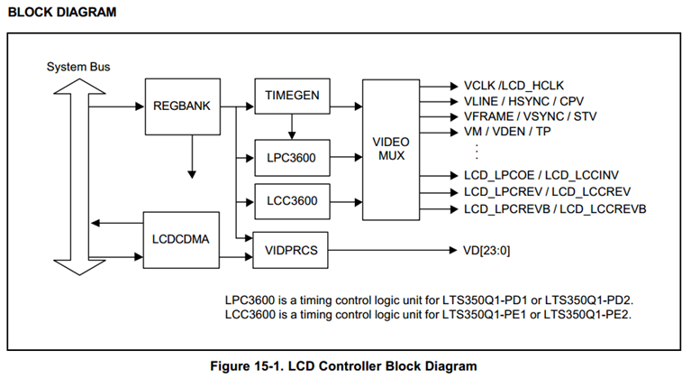
The LCDCDMA is a dedicated DMA, which can transfer the video data in frame memory to LCD driver automatically. By using this special DMA, the video data can be displayed on the screen without CPU intervention.
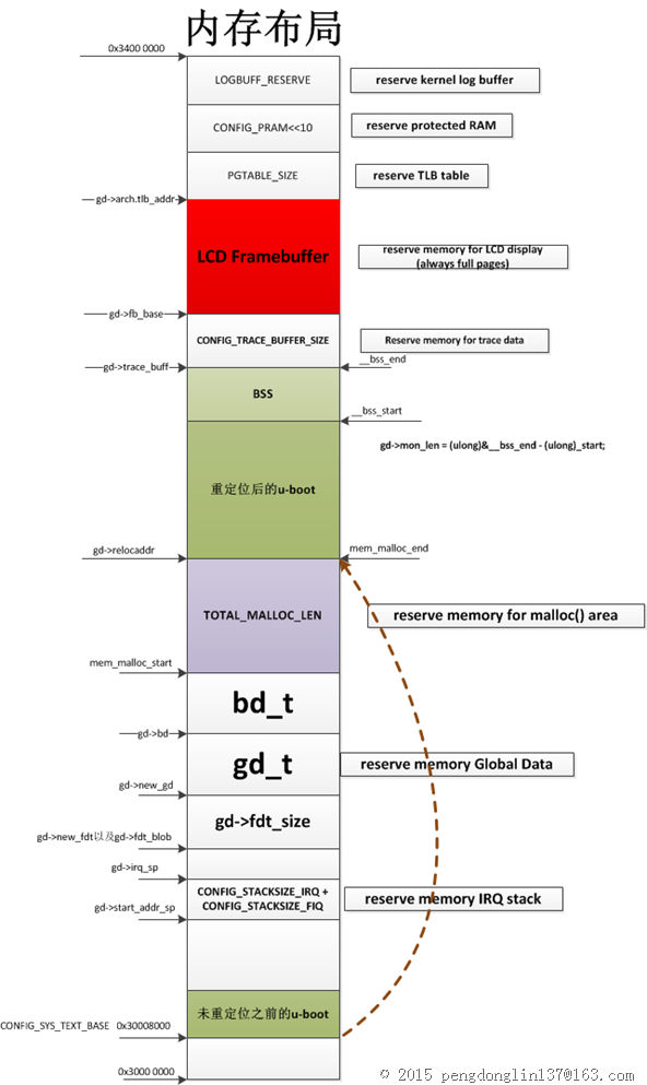
u-boot分配的FrameBuffer:
下图中的红色区域就是u-boot预留的LCD FreamBuffer,它的起始地址存放在gd->fb_base中。
LCD的初始化
下面是函数调用关系:
board_init_r
-> ……
->stdio_init_tables
->initr_serial
->stdio_add_devices (common/stdio.c)
->drv_lcd_init (common/lcd.c)
->lcd_init (common/lcd.c)
下面是lcd_init函数:
1: static int lcd_init(void *lcdbase) 2: { 3: debug("[LCD] Initializing LCD frambuffer at %p\n", lcdbase); 4: lcd_ctrl_init(lcdbase); 5: 6: /* 7: * lcd_ctrl_init() of some drivers (i.e. bcm2835 on rpi) ignores 8: * the 'lcdbase' argument and uses custom lcd base address 9: * by setting up gd->fb_base. Check for this condition and fixup 10: * 'lcd_base' address. 11: */ 12: if (map_to_sysmem(lcdbase) != gd->fb_base) 13: lcd_base = map_sysmem(gd->fb_base, 0); 14: 15: debug("[LCD] Using LCD frambuffer at %p\n", lcd_base); 16: 17: lcd_get_size(&lcd_line_length); 18: lcd_is_enabled = 1; 19: lcd_clear(); 20: lcd_enable(); 21: 22: /* Initialize the console */ 23: lcd_set_col(0); 24: #ifdef CONFIG_LCD_INFO_BELOW_LOGO 25: lcd_set_row(7 + BMP_LOGO_HEIGHT / VIDEO_FONT_HEIGHT); 26: #else 27: lcd_set_row(1); /* leave 1 blank line below logo */ 28: #endif 29: 30: return 0; 31: } 通过分析,最后得知,我们只需要实现函数lcd_ctrl_init、lcd_enable,然后创建一个结构体panel_info,里面填充的是LCD显示屏的分辨率以及每个像素用多少位表示。
我在分析时,参考其他平台的配置文件,将LCD的相关配置打开,然后编译,如果某个函数没有实现,编译时会报错,然后就知道需要实现那些函数。
完成LCD驱动
下面我们就开始完成LCD驱动。
在配置文件中打开相关的配置
文件:include/configs/tq2440.h
8: /* LCD */ 9: #define CONFIG_LCD 10: #define LCD_BPP LCD_COLOR16 11: #define CONFIG_LCD_LOGO /* 显示LOGO */ 12: #undef LCD_TEST_PATTERN 13: #define CONFIG_LCD_INFO /* 显示用户定义的信息 */ 14: #define CONFIG_LCD_INFO_BELOW_LOGO /* 用户自定义的信息与LOGO的位置关系 */ 15: #define CONFIG_SYS_WHITE_ON_BLACK /* 颜色, 黑底白字 */ 16: #define CONFIG_SYS_CONSOLE_IS_IN_ENV 17: 18: #define CONFIG_TQ2440_LCD /* 这个是我自己加的,负责将我添加的文件编译进来 */ 19: 20: #define CONFIG_CONSOLE_MUX /* 这个配置可以支持将u-boot的打印输出同时定向到串口和LCD屏,否则只支持一个 */ 21: 22: /* 23: 下面这些参数是LCD的硬件信息,需要阅读LCD的芯片手册,我使用的LCD的分辨率是480*272,下面的值我选用的 24: 是LCD芯片手册中的典型值,芯片手册的名字:WXCAT43-TG6#001_V1.0.pdf 25: */ 26: #define CONFIG_TQ2440_LCD_VBPD 1 27: #define CONFIG_TQ2440_LCD_VFPD 1 28: #define CONFIG_TQ2440_LCD_VSPW 9 29: #define CONFIG_TQ2440_LCD_HBPD 1 30: #define CONFIG_TQ2440_LCD_HFPD 1 31: #define CONFIG_TQ2440_LCD_HSPW 40 32: #define CONFIG_TQ2440_LCD_CLKVAL 4 33: 34: #define LCD_XSIZE_TFT (480) 35: #define LCD_YSIZE_TFT (272) 36: 37: #define MVAL (13) 38: #define MVAL_USED (0) //0=each frame 1=rate by MVAL 39: #define INVVDEN (1) //0=normal 1=inverted 40: #define BSWP (0) //Byte swap control 41: #define HWSWP (1) //Half word swap control 42: 43: #define CONFIG_SYS_DCACHE_OFF /* 不定义编译的时候会报错 */ 44: 关于这部分可以参考文件:
http://www.cnblogs.com/pengdonglin137/p/4604913.html
定义用户自定义信息
文件:board/samsung/tq2440/tq2440.c
1: root@ubuntu:~/work/latest_codes/u-boot# git diff board/samsung/tq2440/tq2440.c 2: diff --git a/board/samsung/tq2440/tq2440.c b/board/samsung/tq2440/tq2440.c 3: index 3a80f22..d82d410 100644 4: --- a/board/samsung/tq2440/tq2440.c 5: +++ b/board/samsung/tq2440/tq2440.c 6: @@ -13,6 +13,8 @@ 7: #include <netdev.h> 8: #include <asm/io.h> 9: #include <asm/arch/s3c24x0_cpu.h> 10: +#include <lcd.h> 11: +#include <version.h> 12: 13: DECLARE_GLOBAL_DATA_PTR; 14: 15: @@ -143,3 +145,12 @@ ulong board_flash_get_legacy(ulong base, int banknum, flash_info_t *info) 16: info->interface = FLASH_CFI_X16; 17: return 1; 18: } 19: + 20: +#ifdef CONFIG_LCD_INFO 21: +void lcd_show_board_info(void) 22: +{ 23: + lcd_printf ("%s (%s - %s)\n", U_BOOT_VERSION, U_BOOT_DATE, U_BOOT_TIME); 24: + lcd_printf ("(C) 2008 DENX Software Engineering\n"); 25: + lcd_printf (" pengdonglin137@163.com\n"); 26: +} 27: +#endif /* CONFIG_LCD_INFO */
实现LCD初始化和使能函数
我新添加了一个文件:drivers/video/tq2440_fb.c
1: #include <common.h> 2: #include <lcd.h> 3: 4: #include <asm/system.h> 5: #include <asm/gpio.h> 6: #include <asm/arch/s3c24x0_cpu.h> 7: 8: DECLARE_GLOBAL_DATA_PTR; 9: 10: #define U32 unsigned int 11: #define M5D(n) ( ( n ) & 0x1fffff ) // To get lower 21bits 12: #define SCR_XSIZE_TFT LCD_XSIZE_TFT 13: 14: #define HOZVAL_TFT ( LCD_XSIZE_TFT - 1 ) 15: #define LINEVAL_TFT ( LCD_YSIZE_TFT - 1 ) 16: 17: vidinfo_t panel_info = { 18: .vl_col = LCD_XSIZE_TFT, /* 水平分辨率 */ 19: .vl_row = LCD_YSIZE_TFT, /* 垂直分辨率 */ 20: .vl_bpix = LCD_BPP, /* 每个像素用几位表示,这个在 include/configs/tq2440.h中配置了,我使用的是16位 */ 21: }; 22: 23: //volatile unsigned short (*embedsky_LCD_BUFFER)[SCR_XSIZE_TFT] = (volatile unsigned short (*)[SCR_XSIZE_TFT])(gd->fb_base); 24: /* 25: gd->fb_base指向的是FreamBuffer的其实地址,这里我们把它强制转换为一个二维数组来使用 26: */ 27: #define embedsky_LCD_BUFFER ((volatile unsigned short (*)[SCR_XSIZE_TFT])(gd->fb_base)) 28: volatile char vbpd = 1, vfpd = 1, vspw = 1, hbpd = 1, hfpd = 1, hspw = 1, clkval_tft = 1 ; 29: 30: void tq2440_lcd_ClearScr(U32 c) 31: { 32: unsigned int x,y ; 33: 34: for( y = 0 ; y < LCD_YSIZE_TFT ; y++ ) 35: { 36: for( x = 0 ; x < (SCR_XSIZE_TFT) ; x++ ) 37: { 38: embedsky_LCD_BUFFER[y][x] = c; 39: } 40: } 41: 42: } 43: 44: void tq2440_lcd_PowerEnable(int invpwren , int pwren) 45: { 46: struct s3c24x0_gpio * const gpio = s3c24x0_get_base_gpio() ; 47: struct s3c24x0_lcd * const lcd = s3c24x0_get_base_lcd() ; 48: 49: //GPG4 is setted as LCD_PWREN 50: gpio -> gpgup = gpio -> gpgup & (( ~( 1 << 4) ) | ( 1 << 4) ); // Pull-up disable 51: gpio -> gpgcon = gpio -> gpgcon & (( ~( 3 << 8) ) | ( 3 << 8) ); //GPG4=LCD_PWREN 52: gpio -> gpgdat = gpio -> gpgdat | (1 << 4 ) ; 53: //invpwren=pwren; 54: //Enable LCD POWER ENABLE Function 55: lcd -> lcdcon5 = lcd -> lcdcon5 & (( ~( 1 << 3 ) ) | ( pwren << 3 ) ); // PWREN 56: lcd -> lcdcon5 = lcd -> lcdcon5 & (( ~( 1 << 5 ) ) | ( invpwren << 5 ) ); // INVPWREN 57: } 58: 59: void lcd_ctrl_init(void *lcdbase) 60: { 61: struct s3c24x0_gpio * const gpio = s3c24x0_get_base_gpio() ; 62: struct s3c24x0_lcd * const lcd = s3c24x0_get_base_lcd() ; 63: char *s_lcd; 64: 65: lcd -> lcdsaddr1 = ( ( ( U32 ) embedsky_LCD_BUFFER >> 22 ) << 21 ) | M5D ( ( U32 ) embedsky_LCD_BUFFER >> 1 ) ; 66: lcd -> lcdsaddr2 = M5D( ( ( U32) embedsky_LCD_BUFFER + ( SCR_XSIZE_TFT * LCD_YSIZE_TFT * 2 ) ) >> 1 ) ; 67: lcd -> lcdsaddr3 = ( ( ( SCR_XSIZE_TFT - LCD_XSIZE_TFT ) / 1 ) << 11 ) | ( LCD_XSIZE_TFT /1 ) ; 68: 69: s_lcd = getenv ("dwVBPD"); 70: vbpd = s_lcd ? (int)simple_strtol(s_lcd, NULL, 10) : CONFIG_TQ2440_LCD_VBPD; 71: 72: s_lcd = getenv ("dwVFPD"); 73: vfpd = s_lcd ? (int)simple_strtol(s_lcd, NULL, 10) : CONFIG_TQ2440_LCD_VFPD; 74: 75: s_lcd = getenv ("dwVSPW"); 76: vspw = s_lcd ? (int)simple_strtol(s_lcd, NULL, 10) : CONFIG_TQ2440_LCD_VSPW; 77: 78: s_lcd = getenv ("dwHBPD"); 79: hbpd = s_lcd ? (int)simple_strtol(s_lcd, NULL, 10) : CONFIG_TQ2440_LCD_HBPD; 80: 81: s_lcd = getenv ("dwHFPD"); 82: hfpd = s_lcd ? (int)simple_strtol(s_lcd, NULL, 10) : CONFIG_TQ2440_LCD_HFPD; 83: 84: s_lcd = getenv ("dwHSPW"); 85: hspw = s_lcd ? (int)simple_strtol(s_lcd, NULL, 10) : CONFIG_TQ2440_LCD_HSPW; 86: 87: s_lcd = getenv ("dwCLKVAL"); 88: clkval_tft = s_lcd ? (int)simple_strtol(s_lcd, NULL, 10) : CONFIG_TQ2440_LCD_CLKVAL; 89: 90: tq2440_lcd_ClearScr( 0x0 ) ; 91: 92: gpio -> gpcup = 0xffffffff ; 93: gpio -> gpccon = 0xaaaaaaaa ; //Initialize VD[0:7] 94: 95: gpio -> gpdup = 0xffffffff ; 96: gpio -> gpdcon = 0xaaaaaaaa ; //Initialize VD[15:8] 97: 98: lcd -> lcdcon1 = ( clkval_tft << 8 ) | ( MVAL_USED << 7 ) | (3 << 5 ) | ( 12 << 1 ) | 0 ; 99: // TFT LCD panel,16bpp TFT,ENVID=off 100: lcd -> lcdcon2 = ( vbpd << 24 ) | ( LINEVAL_TFT << 14 ) | ( vfpd << 6 ) | ( vspw ) ; 101: lcd -> lcdcon3 = ( hbpd << 19 ) | ( HOZVAL_TFT << 8 ) | ( hfpd ) ; 102: lcd -> lcdcon4 = ( MVAL << 8 ) | ( hspw ) ; 103: lcd -> lcdcon5 = ( 1 << 11) | ( 0 << 10 ) | ( 1 << 9 ) | ( 1 << 8 ) | ( 0 << 7 ) | ( 0 << 6 ) | ( 1 << 3 ) | ( BSWP << 1 ) | ( HWSWP ) ; 104: 105: lcd -> lcdintmsk |= (3) ; // MASK LCD Sub Interrupt 106: lcd -> lpcsel &= ( ~7 ) ; // Disable LPC3480 107: lcd -> tpal = 0x0 ; // Disable Temp Palette 108: 109: tq2440_lcd_PowerEnable( 0, 1 ) ; 110: } 111: 112: void lcd_enable(void) 113: { 114: struct s3c24x0_lcd * const lcd = s3c24x0_get_base_lcd() ; 115: 116: lcd -> lcdcon1 |= 1 ; // ENVID=ON 117: } 由于上面这个文件是新加的,所以要修改相关的Makefile:drivers/video/Makefile
1: diff --git a/drivers/video/Makefile b/drivers/video/Makefile 2: index 22a316b..d6ea213 100644 3: --- a/drivers/video/Makefile 4: +++ b/drivers/video/Makefile 5: @@ -47,3 +47,4 @@ obj-$(CONFIG_VIDEO_VESA) += vesa_fb.o 6: obj-$(CONFIG_FORMIKE) += formike.o 7: obj-$(CONFIG_AM335X_LCD) += am335x-fb.o 8: obj-$(CONFIG_VIDEO_PARADE) += parade.o 9: +obj-$(CONFIG_TQ2440_LCD) += tq2440_fb.o 测试
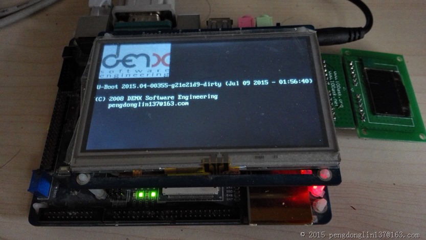
修改完成后,重新编译u-boot,烧写到nandflash,下面是启动画面:
进一步
1.如何把u-boot的打印信息输出到LCD上呢?
上面在include/configs/tq2440.h中我定义了宏:#define CONFIG_CONSOLE_MUX
如果不定义这个宏,u-boot的打印输出只能串口终端或者LCD上,没办法同时输出到两个终端。
接下来,要做的仅仅是修改u-boot环境变量,并且是立即生效。
在u-boot启动后,输入print,可以看到:
1: U-Boot 2015.04-00355-g21e21d9-dirty (Jul 09 2015 - 01:56:40) 2: 3: CPUID: 32440001 4: FCLK: 400 MHz 5: HCLK: 100 MHz 6: PCLK: 50 MHz 7: DRAM: 64 MiB 8: WARNING: Caches not enabled 9: Flash: 0 Bytes 10: NAND: 256 MiB 11: In: serial 12: Out: serial 13: Err: serial 14: Net: dm9000 15: Hit any key to stop autoboot: 0 16: TQ2440 # print 17: baudrate=115200 18: bootargs=noinitrd root=/dev/mtdblock2 rootfstype=yaffs2 init=/linuxrc console=ttySAC0,115200n8 19: bootcmd=nand read 0x30008000 0x200000 0x400000;bootm 0x30008000; 20: bootdelay=3 21: ethact=dm9000 22: ethaddr=00:0c:29:2a:5c:a5 23: ipaddr=192.168.1.6 24: netmask=255.255.255.0 25: serverip=192.168.1.8 26: stderr=serial 27: stdin=serial 28: stdout=serial
其中,第26/27/28行表示stderr、stdin、stdout分别使用的是哪个终端作为输出,这里选用的是串口终端,即serial。
那么,如何定位到LCD呢?
u-boot提供了一个命令,叫做coninfo,执行后:
1: TQ2440 # coninfo 2: List of available devices: 3: lcd 00000002 ..O 4: serial 80000003 SIO stdin stdout stderr 5: s3ser2 00000003 .IO 6: s3ser1 00000003 .IO 7: s3ser0 00000003 .IO 可以看到,一共支持5个终端,lcd表示将lcd屏作为输出终端,最后的O表示这个终端只能输出,不能输入。
serial表示的是串口终端,实际上跟第7行的s3ser0的效果是一样的,因为u-boot默认将串口0作为串口终端,s3ser1和s3ser2分别表示串口1和串口2,tq2440没有这两个串口接出来。
下面我们将stdout设置为s3ser0:
1: TQ2440 # setenv stdout s3ser0 2: TQ2440 # 3: TQ2440 # 4: TQ2440 # print 5: baudrate=115200 6: bootargs=noinitrd root=/dev/mtdblock2 rootfstype=yaffs2 init=/linuxrc console=ttySAC0,115200n8 7: bootcmd=nand read 0x30008000 0x200000 0x400000;bootm 0x30008000; 8: bootdelay=3 9: ethact=dm9000 10: ethaddr=00:0c:29:2a:5c:a5 11: ipaddr=192.168.1.6 12: netmask=255.255.255.0 13: serverip=192.168.1.8 14: stderr=serial 15: stdin=serial 16: stdout=s3ser0 17: 18: Environment size: 357/524284 bytes 19: TQ2440 # coninfo 20: List of available devices: 21: lcd 00000002 ..O 22: serial 80000003 SIO stdin stderr 23: s3ser2 00000003 .IO 24: s3ser1 00000003 .IO 25: s3ser0 00000003 .IO stdout 可以看到,串口工作还正常。
下面我们将LCD作为输出终端:
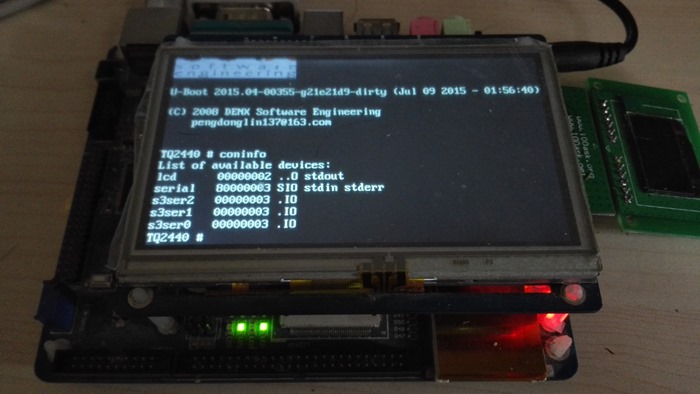
TQ2440 # setenv stdout lcd 执行这句后,串口终端就不会有任何输出,但是可以输入,因为stdin还是serial,输出的信息全部到了lcd上:
下面我们将输出同时从serial和lcd上输出:
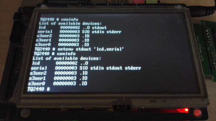
setenv stdout 'lcd,serial' 下面是lcd输出:
下面是串口输出:

完。
这篇关于u-boot支持LCD显示(基于TQ2440)的文章就介绍到这儿,希望我们推荐的文章对编程师们有所帮助!


