本文主要是介绍USB2.0 Spec,希望对大家解决编程问题提供一定的参考价值,需要的开发者们随着小编来一起学习吧!
USB System Description
A USB system is described by three definitional areas:
• USB interconnect
• USB devices
• USB host
USB interconnect
The USB interconnect is the manner in which USB devices are connected to and communicate with the host.
USB Host
There is only one host in any USB system.
The USB interface to the host computer system is referred to as the Host Controller.
The Host Controller may be implemented in a combination of hardware, firmware, or software.
A root hub is integrated within the host system to provide one or more attachment points.
USB Devices
USB devices are one of the following:
• Hubs, which provide additional attachment points to the USB
• Functions, which provide capabilities to the system, such as an ISDN connection, a digital joystick, or speakers
Function <==> Device
USB devices are divided into device classes such as hub, human interface, printer, imaging, or mass storage
device.
All USB devices are accessed by a USB address that is assigned when the device is attached and
enumerated.
Electrical
The USB transfers signal and power over a four-wire cable,The signaling occurs over
two wires on each point-to-point segment.
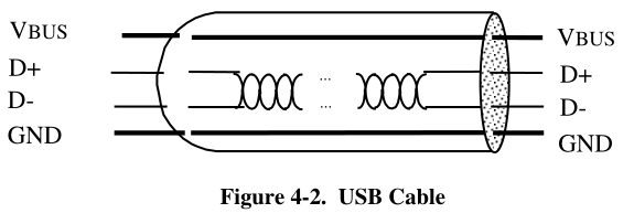
Power
The cable also carries VBUS and GND wires on each segment to deliver power to devices. VBUS is
nominally +5 V at the source.
data rates
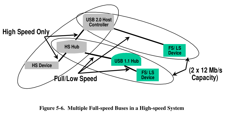
• The USB high-speed signaling bit rate is 480 Mb/s.
• The USB full-speed signaling bit rate is 12 Mb/s.
• A limited capability low-speed signaling mode is also defined at 1.5 Mb/s.
Clock
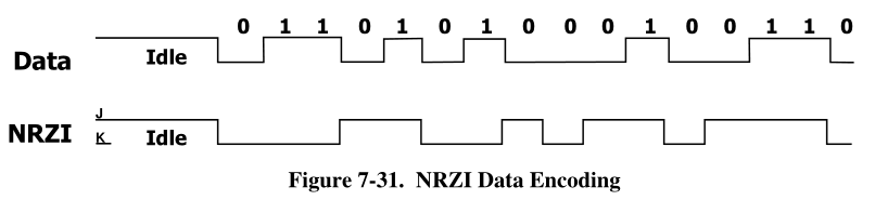
The clock is transmitted, encoded along with the differential data. The clock encoding scheme is NRZI
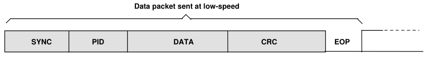
with bit stuffing to ensure adequate transitions. A SYNC field precedes each packet to allow the receiver(s)
to synchronize their bit recovery clocks.
In NRZI encoding, a “1” is represented by no change in level and a “0” is represented by a change in level.
Attachment of USB Devices
All USB devices attach to the USB through ports on specialized USB devices known as hubs. Hubs have
status bits that are used to report the attachment or removal of a USB device on one of its ports. The host
queries the hub to retrieve these bits. In the case of an attachment, the host enables the port and addresses
the USB device through the device’s control pipe at the default address.
The host assigns a unique USB address to the device and then determines if the newly attached USB device
is a hub or a function.
If the attached USB device is a hub and USB devices are attached to its ports, then the above procedure is
followed for each of the attached USB devices.
If the attached USB device is a function, then attachment notifications will be handled by host software that
is appropriate for the function.
Removal of USB Devices
When a USB device has been removed from one of a hub’s ports, the hub disables the port and provides an
indication of device removal to the host. The removal indication is then handled by appropriate USB
System Software. If the removed USB device is a hub, the USB System Software must handle the removal
of both the hub and of all of the USB devices that were previously attached to the system through the hub.
Bus Enumeration
Bus enumeration is the activity that identifies and assigns unique addresses to devices attached to a bus.
Because the USB allows USB devices to attach to or detach from the USB at any time, bus enumeration is
an on-going activity for the USB System Software.
Data Flow Types
- Control Transfers
- Control data is used by the USB System Software to configure devices when they are first attached
- Bulk Data Transfer
- Bulk data typically consists of larger amounts of data, such as that used for printers or scanners.
- Bulk data is sequential.
- Interrupt Data Transfers
- Isochronous Data Transfers
A pipe supports only one of the types of transfers described above for any given device configuration.
Physical Bus Topology
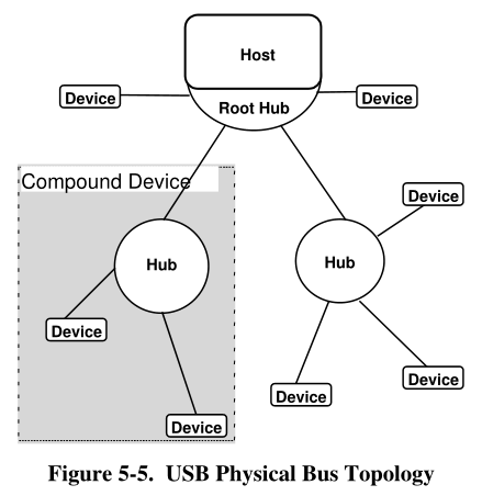
A composite device has only a single device address.
A device that has multiple interfaces controlled independently of each other is referred to as a composite device.
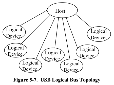
Logical Bus Topology
While devices physically attach to the USB in a tiered, star topology, the host communicates with each
logical device as if it were directly connected to the root port.
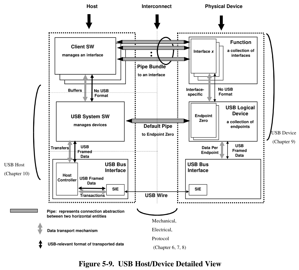
USB Communication Flow
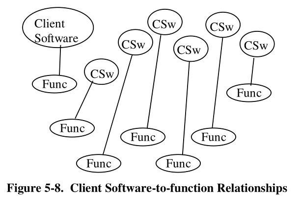
Client Software-to-function Relationship
EndPoints
An endpoint is a uniquely identifiable portion of a USB device that is the terminus of a communication flow
between the host and device.
Each endpoint on a device is given at design time a unique device-determined identifier called the endpoint
number.
The combination of the device address, endpoint number, and direction allows each endpoint to be uniquely referenced.
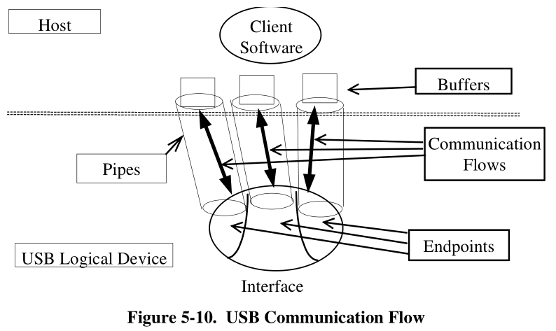
Pipes
A USB pipe is an association between an endpoint on a device and software on the host.
Pipes represent the ability to move data between software on the host via a memory buffer and an endpoint on a device.
There are two mutually exclusive pipe communication modes:
• Stream: Data moving through a pipe has no USB-defined structure
• Message: Data moving through a pipe has some USB-defined structure
Transfer Management
Mechanical
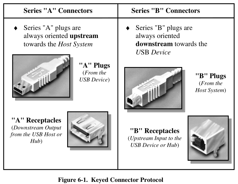
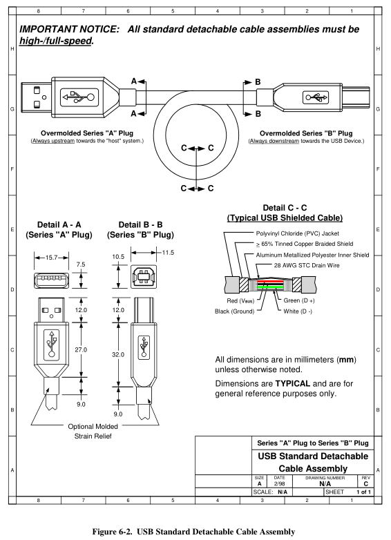
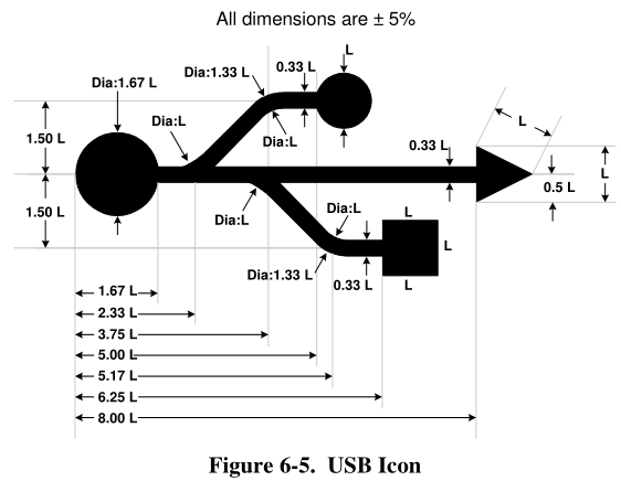
Icon
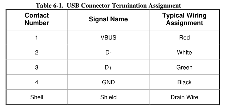
USB Connector Termination Data
Frame
USB Device States
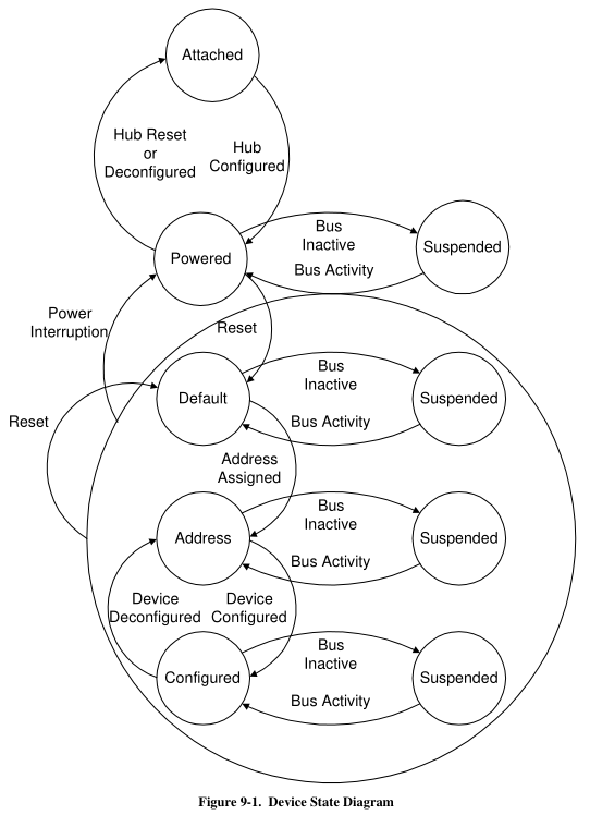
- Attached
- Powered
- USB devices may obtain power from an external source and/or from the USB through the hub to which they
are attached.
- USB devices may obtain power from an external source and/or from the USB through the hub to which they
- Default
- After the device has been powered, it must not respond to any bus transactions until it has received a reset
from the bus.After receiving a reset, the device is then addressable at the default address.
- After the device has been powered, it must not respond to any bus transactions until it has received a reset
- Address
- All USB devices use the default address when initially powered or after the device has been reset.
- Each USB device is assigned a unique address by the host after attachment or after reset.
- A USB device responds to requests on its default pipe whether the device is currently assigned a unique
address or is using the default address.
- Configured
- Before a USB device’s function may be used, the device must be configured.
- Suspended
- In order to conserve power, USB devices automatically enter the Suspended state when the device has
observed no bus traffic for a specified period.
- In order to conserve power, USB devices automatically enter the Suspended state when the device has
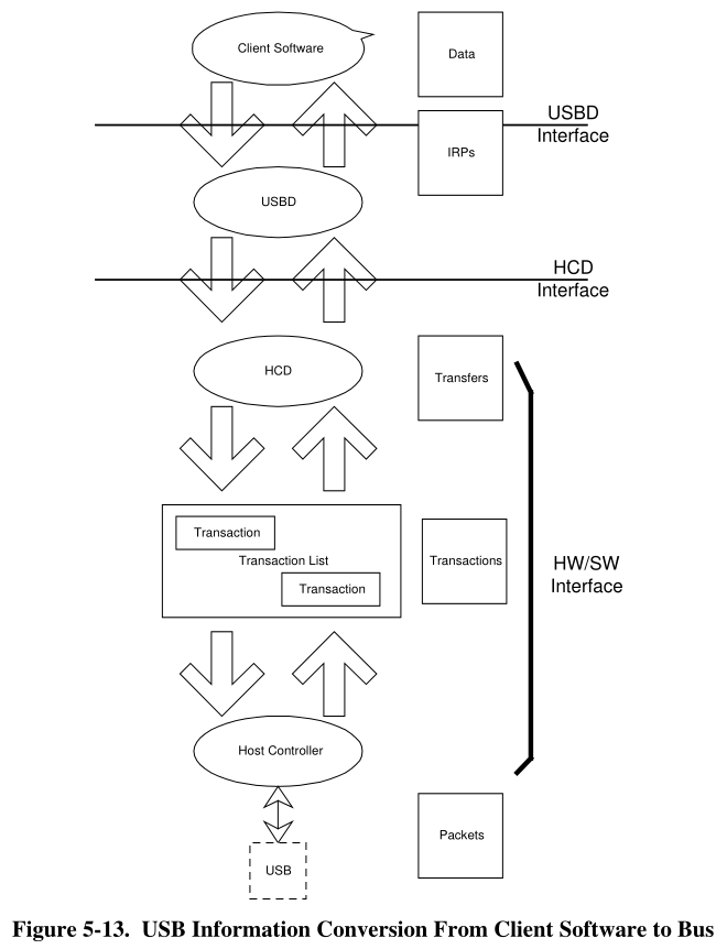
USB Host
The USB System has three basic components:
• Host Controller Driver
• USB Driver
• Host Software
The Host Controller Driver (HCD) exists to more easily map the various Host Controller implementations
into the USB System, such that a client can interact with its device without knowing to which Host
Controller the device is connected.
The USB Driver (USBD) provides the basic host interface (USBDI) for clients to USB devices.
The client layer describes all the software entities that are responsible for directly interacting with USB
devices.
Device Configuration
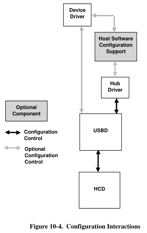
When a device is attached, the hub driver receives a notification from the hub detecting the change.
The hub driver, using the information provided by the hub, requests a device identifier from the USBD.
The device is now ready to be configured for use. For each device, there are three configurations that must
be complete before that device is ready for use:
- Device Configuration: This includes setting up all of the device’s USB parameters and allocating all
USB host resources that are visible to the device. This is accomplished by setting the configuration
value on the device. A limited set of configuration changes, such as alternate settings, is allowed
without totally reconfiguring the device. Once the device is configured, it is, from its point of view,
ready for use. - USB Configuration: In order to actually create a USBD pipe ready for use by a client, additional USB
information, not visible to the device, must be specified by the client. This information, known as the
Policy for the pipe, describes how the client will use the pipe. This includes such items as the
maximum amount of data the client will transfer with one IRP, the maximum service interval the client
will use, the client’s notification identification, and so on. - Function Configuration: Once configuration types 1 and 2 have been accomplished, the pipe is
completely ready for use from the USB’s point of view. However, additional vendor- or class-specific
setup may be required before the client can actually use the pipe. This configuration is a private matter
between the device and the client and is not standardized by the USBD.
这篇关于USB2.0 Spec的文章就介绍到这儿,希望我们推荐的文章对编程师们有所帮助!