本文主要是介绍神州数码DCN交换机 三层功能配置,希望对大家解决编程问题提供一定的参考价值,需要的开发者们随着小编来一起学习吧!
目录
IPv4三层功能配置
一、组网说明
二、组网图
三、配置步骤
IPv4路由典型配置-RIP
一、组网说明
二、组网图
三、配置步骤
四、注意事项
IPv4路由典型配置-OSPF
一、组网说明
二、组网图
三、配置步骤
IPv4路由典型配置-BGP
一、组网说明
二、组网图
三、配置步骤
四、注意事项
IPv6三层功能配置
一、组网说明
二、组网图
三、配置步骤
IPv6隧道功能配置
一、组网说明
二、组网图
三、配置步骤
四、注意事项
IPv6路由功能-RIPng
一、组网说明
二、组网图
三、配置步骤
IPv6路由功能-RIPng
一、组网说明
二、组网图
三、配置步骤
IPv6路由功能-OSPFv3
一、组网说明
二、组网图
三、配置步骤
IPv6路由功能-MBGP4+
一、组网说明
二、组网图
三、配置步骤
VRRP功能典型配置
一、组网说明
二、组网图
三、配置步骤
四、注意事项
VRRPv3功能典型配置
一、组网说明
二、组网图
三、配置步骤
四、注意事项
ARP攻击防护
一、组网说明
二、组网图
三、配置步骤
四、注意事项
keepalive gateway 配置
一、组网说明
二、组网图
三、配置步骤
四、注意事项
防ARP扫描
一、组网说明
二、组网图
三、配置步骤
IPv4三层功能配置
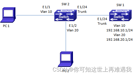
一、组网说明
为三层交换机配置接口地址。
二、组网图

三、配置步骤
#创建Vlan并配置三层接口地址
switch(config)#interface vlan 10
switch(config-If-Vlan10)#ip address 192.168.10.1 255.255.255.0
switch(config-If-Vlan10)#exit
switch(config)#interface vlan 20
switch(config-If-Vlan20)#ip address 192.168.20.1 255.255.255.0
switch(config-If-Vlan20)#exit
switch(config)#interface vlan 30
switch(config-If-Vlan30)#ip address 192.168.30.1 255.255.255.0
switch(config-If-Vlan30)#exit
IPv4路由典型配置-RIP
一、组网说明
三台设备间运行RIP协议。
二、组网图
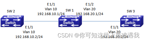
三、配置步骤
三层接口IP地址配置(略)
SW 1的配置
Switch(config)#router rip
Switch(config-router)#network vlan 10
Switch(config-router)#network vlan 20
Switch(config-router)#exit
SW 2的配置
Switch(config)#router rip
Switch(config-router)#network vlan 10
Switch(config-router)#exit
SW 3的配置
Switch(config)#router rip
Switch(config-router)#network vlan 20
Switch(config-router)#exit
四、注意事项
1.运行RIP的设备所配置的三层接口掩码需要相同
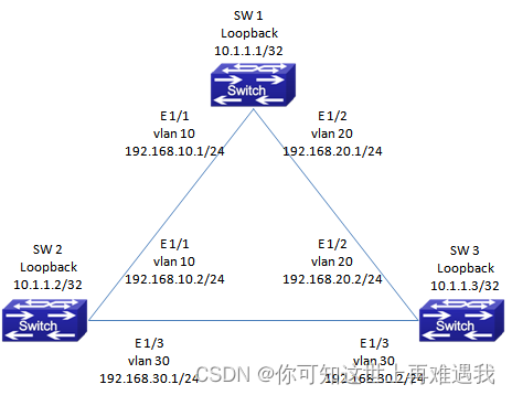
IPv4路由典型配置-OSPF
一、组网说明
网络中的三台设备运行OSPF协议,接口地址如下图。配置单区OSPF协议确保三台设备之间可以互访。
二、组网图
三、配置步骤
SW 1的配置
#配置三层接口地址及Loopback接口地址
switch(config)#interface vlan 10
switch(config-If-Vlan10)#ip address 192.168.10.1 255.255.255.0
switch(config-If-Vlan10)#exit
switch(config)#interface vlan 20
switch(config-If-Vlan20)#ip address 192.168.20.1 255.255.255.0
switch(config-If-Vlan20)#exit
switch(config)#interface loopback 1
switch(config-If-loopback1)#ip address 10.1.1.1 255.255.255.255
switch(config-If-loopback1)#exit
#配置OSPF协议,宣告设备所连的网段
switch(config)#router ospf
switch(config-router)#router-id 10.1.1.1
switch(config-router)#nework 192.168.10.1/24 area 0
switch(config-router)#nework 192.168.20.1/24 area 0
switch(config-router)#exit
SW 2的配置
#配置三层接口地址及Loopback接口地址
switch(config)#interface vlan 10
switch(config-If-Vlan10)#ip address 192.168.10.2 255.255.255.0
switch(config-If-Vlan10)#exit
switch(config)#interface vlan 30
switch(config-If-Vlan30)#ip address 192.168.30.1 255.255.255.0
switch(config-If-Vlan30)#exit
switch(config)#interface loopback 1
switch(config-If-loopback1)#ip address 10.1.1.2 255.255.255.255
switch(config-If-loopback1)#exit
#配置OSPF协议,宣告设备所连的网段
switch(config)#router ospf
switch(config-router)#router-id 10.1.1.2
switch(config-router)#nework 192.168.10.1/24 area 0
switch(config-router)#nework 192.168.30.1/24 area 0
switch(config-router)#exit
SW 3的配置
#配置三层接口地址及Loopback接口地址
switch(config)#interface vlan 20
switch(config-If-Vlan20)#ip address 192.168.20.2 255.255.255.0
switch(config-If-Vlan20)#exit
switch(config)#interface vlan 30
switch(config-If-Vlan30)#ip address 192.168.30.2 255.255.255.0
switch(config-If-Vlan30)#exit
switch(config)#interface loopback 1
switch(config-If-loopback1)#ip address 10.1.1.3 255.255.255.255
switch(config-If-loopback1)#exit
#配置OSPF协议,宣告设备所连的网段
switch(config)#router ospf
switch(config-router)#router-id 10.1.1.3
switch(config-router)#nework 192.168.20.1/24 area 0
switch(config-router)#nework 192.168.30.1/24 area 0
switch(config-router)#exit
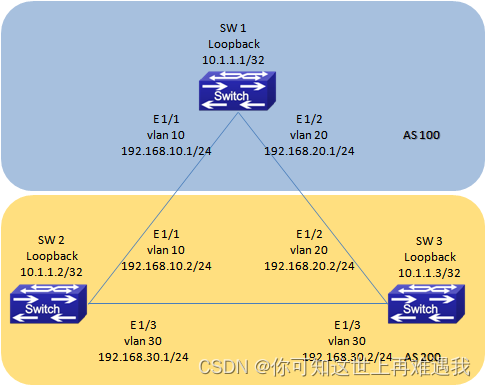
IPv4路由典型配置-BGP
一、组网说明
三台设备运行BGP协议,SW 1属于AS 100,SW 2和SW 3属于AS 200。配置BGP协议,以保证三台设备之间可以互通。
二、组网图
三、配置步骤
SW 1的配置
#BGP部分
switch(config)#router bgp 100
switch(config-router-bgp)#bgp router-id 10.1.1.1
switch(config-router-bgp)#network 192.168.10.1/24
switch(config-router-bgp)#network 192.168.20.1/24
switch(config-router-bgp)#neighbor 10.1.1.2 remote-as 200
switch(config-router-bgp)#neighbor 10.1.1.3 remote-as 200
switch(config-router-bgp)#exit
SW 2的配置
#BGP部分
switch(config)#router bgp 200
switch(config-router-bgp)#bgp router-id 10.1.1.2
switch(config-router-bgp)#network 192.168.20.1/24
switch(config-router-bgp)#network 192.168.30.1/24
switch(config-router-bgp)#neighbor 10.1.1.1 remote-as 100
switch(config-router-bgp)#neighbor 10.1.1.3 remote-as 200
switch(config-router-bgp)#exit
SW 3的配置
#BGP部分
switch(config)#router bgp 200
switch(config-router-bgp)#bgp router-id 10.1.1.3
switch(config-router-bgp)#network 192.168.10.1/24
switch(config-router-bgp)#network 192.168.30.1/24
switch(config-router-bgp)#neighbor 10.1.1.1 remote-as 100
switch(config-router-bgp)#neighbor 10.1.1.2 remote-as 200
switch(config-router-bgp)#exit
四、注意事项
1.建立邻居关系时,两台设备间可以不直接连接。但需要确保有IGP路由可达。
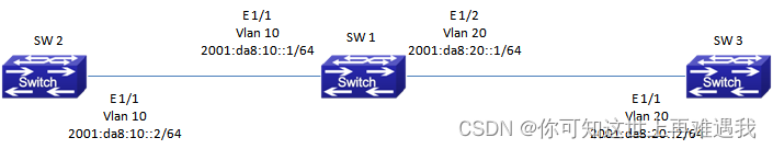
IPv6三层功能配置
一、组网说明
为交换机配置IPv6接口地址,并开启路由公告功能,确保下联的PC可以获得IPv6无状态地址。
二、组网图

三、配置步骤
#全局打开IPv6功能,并配置接口地址
Switch(Config)#ipv6 enable
Switch(Config)#interface vlan 10
Switch(Config-if-Vlan10)#ipv6 address 2001:da8:10::1/64
Switch(Config-if-Vlan10)#no ipv6 nd suppress-ra
Switch(Config-if-Vlan10)#exit
Switch(Config)#interface vlan 20
Switch(Config-if-Vlan20)#ipv6 address 2001:da8:20::1/64
Switch(Config-if-Vlan20)#no ipv6 nd suppress-ra
Switch(Config-if-Vlan20)#exit
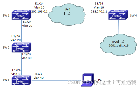
IPv6隧道功能配置
一、组网说明
SW 1和SW 4分别属于两个不同的部门,中间通过IPv4链路互联。在SW 4下面带有IPv6的网络。
要求: 1.通过配置隧道,使SW 1和SW 4之间通过IPv4地址建立IPv6连接,分配给SW 1使用的IPv6地址段为2001:da8:10::/24段。
2.SW 4和SW 1隧道互联使用的IPv6地址分别为2001:da8:1::1/64和2001:da8:1::2/64。
3.SW 2设备支持IPv6,但SW 3设备并不支持IPv6。为了保证PC可以使用IPv6地址访问IPv6资源,在SW 2上配置ISATAP隧道,为用户分配2001:da8:10:40::1/64的地址段。
二、组网图
三、配置步骤
SW 4的配置
#配置IPv6配置隧道,并将IPv6路由指向隧道接口
switch(config)#interface tunnel 1
switch(config-If-Tunnel1)#ipv6 address 2001:da8:1::1/64
switch(config-If-Tunnel1)#tunnel source 218.240.1.1
switch(config-If-Tunnel1)#tunnel destination 202.106.0.1
switch(config-If-Tunnel1)#tunnel mode ipv6ip
switch(config-If-Tunnel1)#exit
switch(config)#ipv6 route 2001:da8:10::/24 tunnel 1
SW 1的配置
#配置IPv6配置隧道,并将IPv6路由指向隧道接口
switch(config)#interface tunnel 1
switch(config-If-Tunnel1)#ipv6 address 2001:da8:1::2/64
switch(config-If-Tunnel1)#tunnel source 202.106.0.1
switch(config-If-Tunnel1)#tunnel destination 218.240.1.1
switch(config-If-Tunnel1)#tunnel mode ipv6ip
switch(config-If-Tunnel1)#exit
switch(config)#ipv6 route 2001:da8::/16 tunnel 1
SW 2的配置
#配置ISATAP隧道
switch(config)#interface tunnel 1
switch(config-If-Tunnel1)#ipv6 nd prefix 2001:da8:10:40::1/64
switch(config-If-Tunnel1)#no ipv6 nd suppress-ra
switch(config-If-Tunnel1)#tunnel source 192.168.30.1
switch(config-If-Tunnel1)#tunnel nexthop 192.168.30.2
switch(config-If-Tunnel1)#tunnel mode isatap
switch(config-If-Tunnel1)#exit
switch(config)#ipv6 route 2001:da8:10:40::/64 tunnel 1
四、注意事项
1.配置ISATAP隧道时,配置命令和IPv6配置隧道有区别。
2.PC机要连接到ISATAP隧道,还需要在CMD窗口中输入netsh命令后再输入“interface ipv6 isatap set router 192.168.30.1”最后的IP地址是ISATAP隧道设备中配置的隧道源地址。
IPv6路由功能-RIPng
一、组网说明
三台设备运行RIPng。
二、组网图
三、配置步骤
SW 1的配置
Switch(Config)#ipv6 enable
Switch(config)#router ipv6 rip
Switch(config-router)#exit
Switch(config)#interface Vlan 10
Switch(config-if-Vlan10)#ipv6 address 2000:da8:10::1/64
Switch(config-if-Vlan10)#ipv6 router rip
Switch(config-if-Vlan10)#exit
Switch(config)#interface Vlan 20
Switch(config-if-Vlan20)#ipv6 address 2000:da8:20::1/64
Switch(config-if-Vlan20)#ipv6 router rip
Switch(config-if-Vlan20)#exit
SW 2的配置
Switch(Config)#ipv6 enable
Switch(config)#router ipv6 rip
Switch(config-router)#exit
Switch(config)#interface Vlan 10
Switch(config-if-Vlan10)#ipv6 address 2000:da8:10::2/64
Switch(config-if-Vlan10)#ipv6 router rip
Switch(config-if-Vlan10)#exit
SW 3的配置
Switch(Config)#ipv6 enable
Switch(config)#router ipv6 rip
Switch(config-router)#exit
Switch(config)#interface Vlan 20
Switch(config-if-Vlan20)#ipv6 address 2000:da8:20::2/64
Switch(config-if-Vlan20)#ipv6 router rip
Switch(config-if-Vlan20)#exit
IPv6路由功能-RIPng
一、组网说明
三台设备运行RIPng。
二、组网图

三、配置步骤
SW 1的配置
Switch(Config)#ipv6 enable
Switch(config)#router ipv6 rip
Switch(config-router)#exit
Switch(config)#interface Vlan 10
Switch(config-if-Vlan10)#ipv6 address 2000:da8:10::1/64
Switch(config-if-Vlan10)#ipv6 router rip
Switch(config-if-Vlan10)#exit
Switch(config)#interface Vlan 20
Switch(config-if-Vlan20)#ipv6 address 2000:da8:20::1/64
Switch(config-if-Vlan20)#ipv6 router rip
Switch(config-if-Vlan20)#exit
SW 2的配置
Switch(Config)#ipv6 enable
Switch(config)#router ipv6 rip
Switch(config-router)#exit
Switch(config)#interface Vlan 10
Switch(config-if-Vlan10)#ipv6 address 2000:da8:10::2/64
Switch(config-if-Vlan10)#ipv6 router rip
Switch(config-if-Vlan10)#exit
SW 3的配置
Switch(Config)#ipv6 enable
Switch(config)#router ipv6 rip
Switch(config-router)#exit
Switch(config)#interface Vlan 20
Switch(config-if-Vlan20)#ipv6 address 2000:da8:20::2/64
Switch(config-if-Vlan20)#ipv6 router rip
Switch(config-if-Vlan20)#exit
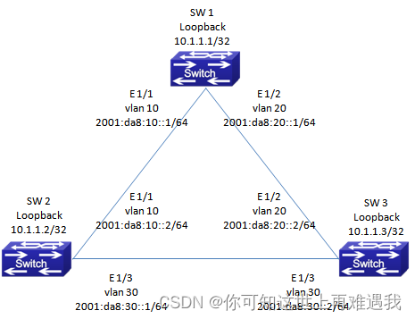
IPv6路由功能-OSPFv3
一、组网说明
网络中的三台设备运行OSPFv3协议,接口地址如下图。配置单区OSPFv3协议确保三台设备之间可以互访。
二、组网图
三、配置步骤
SW 1的配置
#打开IPv6功能,配置三层接口和LoopBack接口
switch(config)#ipv6 enable
switch(config)#interface vlan 10
switch(config-If-Vlan10)#ipv6 address 2001:da8:10::1/64
switch(config-If-Vlan10)#exit
switch(config)#interface vlan 20
switch(config-If-Vlan20)#ipv6 address 2001:da8:20::1/64
switch(config-If-Vlan20)#exit
switch(config)#interface loopback 1
switch(config-If-loopback1)#ip address 10.1.1.1 255.255.255.255
switch(config-If-loopback1)#exit
#配置OSPFv3
switch(config)#router ipv6 ospf
switch(config-router)#router-id 10.1.1.1
switch(config-router)#exit
switch(config)#interface vlan 10
switch(config-If-Vlan10)#ipv6 router ospf area 0
switch(config-If-Vlan10)#exit
switch(config)#interface vlan 20
switch(config-If-Vlan20)#ipv6 router ospf area 0
switch(config-If-Vlan20)#exit
SW 2的配置
#打开IPv6功能,配置三层接口和LoopBack接口
switch(config)#ipv6 enable
switch(config)#interface vlan 10
switch(config-If-Vlan10)#ipv6 address 2001:da8:10::2/64
switch(config-If-Vlan10)#exit
switch(config)#interface vlan 30
switch(config-If-Vlan30)#ipv6 address 2001:da8:30::1/64
switch(config-If-Vlan30)#exit
switch(config)#interface loopback 1
switch(config-If-loopback1)#ip address 10.1.1.2 255.255.255.255
switch(config-If-loopback1)#exit
#配置OSPFv3
switch(config)#router ipv6 ospf
switch(config-router)#router-id 10.1.1.2
switch(config-router)#exit
switch(config)#interface vlan 10
switch(config-If-Vlan10)#ipv6 router ospf area 0
switch(config-If-Vlan10)#exit
switch(config)#interface vlan 30
switch(config-If-Vlan20)#ipv6 router ospf area 0
switch(config-If-Vlan20)#exit
SW 3的配置
#打开IPv6功能,配置三层接口和LoopBack接口
switch(config)#ipv6 enable
switch(config)#interface vlan 20
switch(config-If-Vlan20)#ipv6 address 2001:da8:20::2/64
switch(config-If-Vlan20)#exit
switch(config)#interface vlan 30
switch(config-If-Vlan30)#ipv6 address 2001:da8:30::2/64
switch(config-If-Vlan30)#exit
switch(config)#interface loopback 1
switch(config-If-loopback1)#ip address 10.1.1.3 255.255.255.255
switch(config-If-loopback1)#exit
#配置OSPFv3
switch(config)#router ipv6 ospf
switch(config-router)#router-id 10.1.1.3
switch(config-router)#exit
switch(config)#interface vlan 20
switch(config-If-Vlan10)#ipv6 router ospf area 0
switch(config-If-Vlan10)#exit
switch(config)#interface vlan 30
switch(config-If-Vlan20)#ipv6 router ospf area 0
switch(config-If-Vlan20)#exit
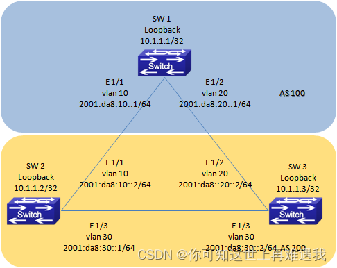
IPv6路由功能-MBGP4+
一、组网说明
三台设备运行MBGP4+协议,SW 1属于AS 100,SW 2和SW 3属于AS 200。配置MBGP4+协议,以保证三台设备之间可以互通。
二、组网图
三、配置步骤
SW 1的配置
#MBGP4+部分
switch(config)#router bgp 100
switch(config-router)#bgp router-id 10.1.1.1
switch(config-router)#neighbor 2001:da8:10::2 remote-as 200
switch(config-router)#neighbor 2001:da8:20::2 remote-as 200
switch(config-router)#address-family ipv6 unicast
switch(config-router-af)#neighbor 2001:da8:10::2 activate
switch(config-router-af)#neighbor 2001:da8:20::2 activate
switch(config-router-af)#exit-address-family
switch(config-router)#exit
SW 2的配置
#MBGP4+部分
switch(config)#router bgp 200
switch(config-router)#bgp router-id 10.1.1.2
switch(config-router)#neighbor 2001:da8:10::1 remote-as 100
switch(config-router)#neighbor 2001:da8:30::2 remote-as 200
switch(config-router)#address-family ipv6 unicast
switch(config-router-af)#neighbor 2001:da8:10::1 activate
switch(config-router-af)#neighbor 2001:da8:30::2 activate
switch(config-router-af)#exit-address-family
switch(config-router)#exit
SW 3的配置
#MBGP4+部分
switch(config)#router bgp 200
switch(config-router)#bgp router-id 10.1.1.3
switch(config-router)#neighbor 2001:da8:20::1 remote-as 100
switch(config-router)#neighbor 2001:da8:30::1 remote-as 200
switch(config-router)#address-family ipv6 unicast
switch(config-router-af)#neighbor 2001:da8:20::1 activate
switch(config-router-af)#neighbor 2001:da8:30::1 activate
switch(config-router-af)#exit-address-family
switch(config-router)#exit
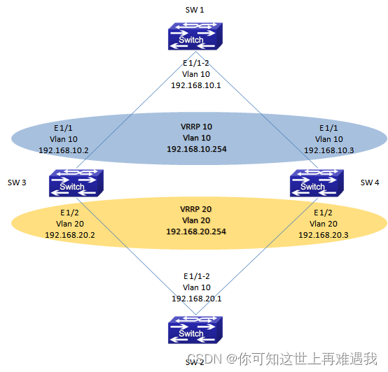
VRRP功能典型配置
一、组网说明
SW 3和SW 4两台交换机运行VRRP协议,为SW 1和SW 2提供虚拟网关服务,以保证SW 3和SW 4任意一台设备或链路中断的情况下SW 1还可以和SW 2通讯。
二、组网图
三、配置步骤
SW 3的配置
#配置Vlan和三层接口
switch(config)#vlan 10
switch(config-Vlan10)#switchport interface ethernet address 1/1
switch(config-Vlan10)#ip address 192.168.10.2 255.255.255.0
switch(config-Vlan10)#exit
switch(config)#vlan 20
switch(config-Vlan20)#switchport interface ethernet address 1/2
switch(config-Vlan20)#ip address 192.168.20.2 255.255.255.0
switch(config-Vlan20)#exit
#配置VRRP
switch(config)#router vrrp 10
switch(config-router)#virtual-ip 192.168.10.254
switch(config-router)#interface vlan 10
switch(config-router)#priority 120
switch(config-router)#enable
switch(config-router)#exit
switch(config)#router vrrp 20
switch(config-router)#virtual-ip 192.168.20.254
switch(config-router)#interface vlan 20
switch(config-router)#priority 120
switch(config-router)#enable
switch(config-router)#exit
SW 4的配置
#配置Vlan和三层接口
switch(config)#vlan 10
switch(config-Vlan10)#switchport interface ethernet address 1/1
switch(config-Vlan10)#ip address 192.168.10.3 255.255.255.0
switch(config-Vlan10)#exit
switch(config)#vlan 20
switch(config-Vlan20)#switchport interface ethernet address 1/2
switch(config-Vlan20)#ip address 192.168.20.3 255.255.255.0
switch(config-Vlan20)#exit
#配置VRRP
switch(config)#router vrrp 10
switch(config-router)#virtual-ip 192.168.10.254
switch(config-router)#interface vlan 10
switch(config-router)#enable
switch(config-router)#exit
switch(config)#router vrrp 20
switch(config-router)#virtual-ip 192.168.20.254
switch(config-router)#interface vlan 20
switch(config-router)#enable
switch(config-router)#exit
四、注意事项
1.VRRP配置完成后,必须使用enable命令将VRRP使能。否则VRRP配置不生效。在修改VRRP组的配置时,也需要先将VRRP组Disable后才可以修改VRRP组的配置。
2.VRRP组的ID号从1-255,总共可以创建255个VRRP组。
3.VRRP组默认监控的是三层接口的UP/Down,在冗余链路的环境中,需要配合STP协议一起使用,以保证网络的可用性。(后续版本中,可以配合BFD功能监控物理接口的UP/Down)
4.VRRP的交互报文只有定期发送的Hello报文,默认的交互时间是1S。当整机的VRRP组超过10组时,建议修改VRRP的交互间隔,避免设备在同一时间处理大量的VRRP报文。
5.VRRP组根据优先级比较确认那台设备会成为Master,默认的优先级是100。优先级相同时,再比较IP地址,IP地址较大的一台会做为Master。
VRRPv3功能典型配置
一、组网说明
SW 3和SW 4运行VRRPv3协议,为SW 1和SW 2提供IPv6的冗余网关服务。
二、组网图

三、配置步骤
SW 3的配置
#开启配置IPv6,并配置Vlan和三层接口
Switch(Config)#ipv6 enable
switch(config)#vlan 10
switch(config-Vlan10)#switchport interface ethernet 1/1
switch(config-Vlan10)#ipv6 address 2001:da8:10::2/64
switch(config-Vlan10)#exit
switch(config)#vlan 20
switch(config-Vlan20)#switchport interface ethernet 1/2
switch(config-Vlan20)#ipv6 address 2001:da8:20::2/64
switch(config-Vlan20)#exit
#配置VRRPv3
switch(config)#router ipv6 vrrp 10
switch(config-router)#virtual-ipv6 2001:da8:10::ffff interface vlan 10
switch(config-router)#priority 120
switch(config-router)#enable
switch(config-router)#exit
switch(config)#router ipv6 vrrp 20
switch(config-router)#virtual-ipv6 2001:da8:20::ffff interface vlan 20
switch(config-router)#priority 120
switch(config-router)#enable
switch(config-router)#exit
SW 4的配置
#开启配置IPv6,并配置Vlan和三层接口
Switch(Config)#ipv6 enable
switch(config)#vlan 10
switch(config-Vlan10)#switchport interface ethernet 1/1
switch(config-Vlan10)#ipv6 address 2001:da8:10::3/64
switch(config-Vlan10)#exit
switch(config)#vlan 20
switch(config-Vlan20)#switchport interface ethernet 1/2
switch(config-Vlan20)#ipv6 address 2001:da8:20::3/64
switch(config-Vlan20)#exit
#配置VRRP
switch(config)#router ipv6 vrrp 10
switch(config-router)#virtual-ipv6 2001:da8:10::ffff interface vlan 10
switch(config-router)#enable
switch(config-router)#exit
switch(config)#router ipv6 vrrp 20
switch(config-router)#virtual-ipv6 2001:da8:20::ffff interface vlan 20
switch(config-router)#enable
switch(config-router)#exit
四、注意事项
1.VRRP配置完成后,必须使用enable命令将VRRP使能。否则VRRP配置不生效。在修改VRRP组的配置时,也需要先将VRRP组Disable后才可以修改VRRP组的配置。
2.VRRP组的ID号从1-255,总共可以创建255个VRRP组。
3.VRRP组默认监控的是三层接口的UP/Down,在冗余链路的环境中,需要配合STP协议一起使用,以保证网络的可用性。(后续版本中,可以配合BFD功能监控物理接口的UP/Down)
4.VRRP的交互报文只有定期发送的Hello报文,默认的交互时间是1S。当整机的VRRP组超过10组时,建议修改VRRP的交互间隔,避免设备在同一时间处理大量的VRRP报文。
5.VRRP组根据优先级比较确认那台设备会成为Master,默认的优先级是100。优先级相同时,再比较IP地址,IP地址较大的一台会做为Master。
ARP攻击防护
一、组网说明
SW 1做为网络中的网关设备,配置了Vlan 10和Vlan 20两个三层接口。SW 2做为接入交换机,连接用户PC。为了防止下联的用户PC产生的ARP欺骗报文景程网络中的其他用户,在SW 2上配置ARP防护相关功能。
二、组网图
三、配置步骤
SW 2的配置
#开启ARP-Guard功能,防止PC机发出网关欺骗报文
Switch(config)#interface ethernet 1/1
Switch(Config-If-Ethernet1/1)#arp-guard ip 192.168.10.1
Switch(config)#exit
Switch(config)#interface ethernet 1/2
Switch(Config-If-Ethernet1/2)#arp-guard ip 192.168.20.1
Switch(config)#exit
#开启Anti-ArpScan功能,防止PC机发出大量ARP影响其他PC
Switch(config)#anti-arpscan enable
Switch(config)#anti-arpscan recovery time 3600
Switch(config)#interface ethernet 1/24
Switch(config-If-Ethernet1/24)#anti-arpscan trust supertrust-port
Switch(config-If-Ethernet1/24)#exit
#针对静态IP用户,使用AM功能防止PC机发出主机欺骗报文。针对动态IP用户,使用DHCP Snooping Binding功能防止PC机发出主机欺骗报文。
AM和DHCP Snooping Binding配置命令略,请参照手册中对应章节
四、注意事项
1.ARP-Guard功能也会占用少许ACL表项。在和其他功能配合使用时,需要注意ACL表项是否可以满足应用需要。一个物理接口下可以配置多条ARP-Guard命令。
2.Anti-ArpScan功能不建议单独使用,建议配合AM或DHCP Snooping Binding功能同时使用。
3.配置Anti-ArpScan功能时,上联口必须配置为SuperTust模式
keepalive gateway 配置
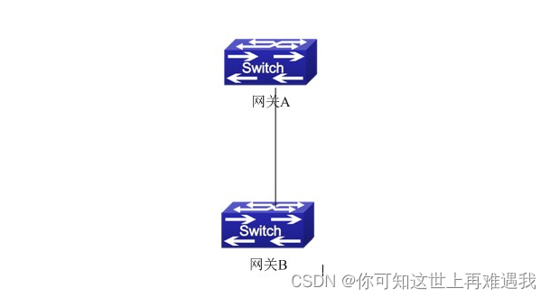
一、组网说明
网关A interface vlan10 接口地址为1.1.1.1 255.255.255.0,网关B interface vlan100接口地址为1.1.1.2 255.255.255.0,网关B支持keepalive gate功能。
二、组网图
三、配置步骤
- 采用默认的发送arp间隔和判定探测失败重复次数(缺省发送arp探测报文周期为10s,缺省判定探测失败重复次数为5次)
Switch(config)#interface vlan 100
Switch(config-if-vlan100)#keepalive gateway 1.1.1.1
Switch(config-if-vlan100)#exit
- 手动配置发送arp间隔和判定探测失败重复次数
Switch(config)#interface vlan 100
Switch(config-if-vlan100)#keepalive gateway 1.1.1.1 3 3
Switch(config-if-vlan100)#exit
探测网关A是否可达,每隔3秒发送一次ARP探测,探测3次失败后认为网关A不可达。
四、注意事项
1.确认设备为三层交换机,二层交换机不支持该功能.
2.该种探测方法仅适用于点对点的拓扑模式。
3。 该方法是探测的IPv4可达性。因此探测结果,只能影响接口的IPv4工作状态。当探测失败时,只能禁止接口上不再运行IPv4业务;但IPv6等其它业务不受该探测的影响。
4. 接口的物理状态仅受物理信号的控制,不受该探测功能的控制。
防ARP扫描
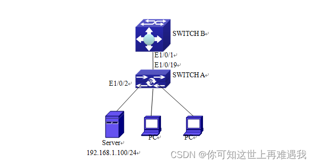
一、组网说明
SWITCH B的端口e1/0/1与SWITCH A的端口e1/0/19相连,SWITCH A上的端口e1/0/2与文件服务器(IP 地址为192.168.1.100/24)相连,其他端口都与普通PC相连。可通过下面的配置有效地防止ARP扫描,而又不影响系统的正常运行。
二、组网图
三、配置步骤
SWITCH A配置任务序列:
SwitchA(config)#anti-arpscan enable
SwitchA(config)#anti-arpscan recovery time 3600
SwitchA(config)#anti-arpscan trust ip 192.168.1.100 255.255.255.0
SwitchA(config)#interface ethernet1/0/2
SwitchA (Config-If-Ethernet1/0/2)#anti-arpscan trust port
SwitchA (Config-If-Ethernet1/0/2)#exit
SwitchA(config)#interface ethernet1/0/19
SwitchA (Config-If-Ethernet1/0/19)#anti-arpscan trust supertrust-port
Switch A(Config-If-Ethernet1/0/19)#exit
SWITCH B配置任务序列:
SwitchB(config)#anti-arpscan enable
SwitchB(config)#interface ethernet1/0/1
SwitchB(Config-If-Ethernet1/0/1)#anti-arpscan trust port
SwitchB(Config-If-Ethernet1/0/1)exit
这篇关于神州数码DCN交换机 三层功能配置的文章就介绍到这儿,希望我们推荐的文章对编程师们有所帮助!